|
|
Post by Tobyjugs on Jan 30, 2022 14:16:51 GMT 1
Idealy a nice smooth running surface is best as everyone has suggested. Bare's suggestion is not so bad I have a pair of forks which i have adjusted for trackdays etc. They also have rust marks which seem to be a little worse than in your picture. To get around the leaking and damaging of seals etc i polish them with some special linishing cloth (its actually platsic). Its made by 3M and is a 30 micron micro-finishing film. It's very fine but sharp at the same time. Hard to describe the action, you can feel it bite in so i use it with WD40. I cut it into a 20mm wide long strips and give the blemishes a quick polish. It doesnt take much time and removes any high points or edges. Until now i've never had any problems with leaks. Of course this method is just like putting a plaster over a wound. Eventually this paper will remove the chrome, but before that happens i might bend the forks in an off.  |
|
|
|
Post by Tobyjugs on Jan 30, 2022 11:12:23 GMT 1
Not such a stupid idea to inflate tyres with another gas other than air. Of course the above was a joke, and would offer negligible benefits for 2 or 3 days until the tyres went flat due to the tiny molecules of helium passing through the tyres or bead. However go the other way with nitrogen (which has a large molecule size) and you have a small improvement over air. Not quite sure how they evacuate the uncompressed air from the tyres first if at all. Anyone know? Jon I just googled it and found this; |
|
|
|
Post by Tobyjugs on Jan 29, 2022 21:33:12 GMT 1
Once isaw a TR on the dyno that vibrated so bad that the fueling in the carbs was affected.
|
|
|
|
Post by Tobyjugs on Jan 29, 2022 21:26:55 GMT 1
Oh nice and shiny John. That's certainly the best way to clean the base gasket area.
|
|
|
|
Post by Tobyjugs on Jan 29, 2022 21:21:11 GMT 1
Time to update this project a bit. Not sure where to begin so i think i will begin with last August /September. September i had a whole month off work so with that in mind i wanted to get the bike out on the track. I was still messing around with the clutch and the output of the engine seemed to be going up and down a bit. I made the clutch super strong and decided to test it on the back roads where i live. This was not a good idea and to be honest i was a little bit disappointed. The roads were too bumpy and the first 3 gears are too short leading straight to wheelies. So back to the dyno bank.  Can't quite recall this piece but due to a low tyre pressure or the weight difference between me and Pieter (the dyno owner) it was noticed the bike made more or less power. This lead to the conclusion the bike had been spinning the rear tyre up on the roller of the dyno bank. A lot of clutch work was done for the wrong reason. So with the bike now being tested with the wheel firmly in place on the dyno bank every thing was fine and the power was reading 97 PK without slip. Pieter suggested we do some runs to check the speed and gearing which i thought was agood idea. So whilst doing this the clutch siezed. Then that sinking feeling came to me as i knew it was my fault. I started out using a steel ball bearing then later swapped it to a ceramic ball bearing because of the thought of it seizing as i was upping the strength of the clutch. The last time i put the clutch together i dropped the ceramic ball on the floor and couldnt find it. Due to me wanting to sort it all before September i put the steel ball bearing back in.  If you click on the picture below you will see the video where the clutch siezed.  It turned out i couldn't pull the clutch actuation shaft out because it had mushroomed on the otherside of the shaft as well. I had to split the engine.  
Pedrotzr came to my rescue and within a few days i had a thrust bearing and i got some more ceramic ball bearings. Just before Xmas i found the original ceramic bearing on the floor. When i first decided to build this project i asked Pieter from PS=Tuning to help me. He was very enthusiastic but he had one condltion. This was that we keep the engine power at around 85-90 PK he knew Kees would also be riding this bike and wanted to make sure that it wasn't too harsh. He said to me "i know you will be afraid of it and throttle off, but Kees won't". I totally agreed with him on that. After i repaired the siezed clutch mechanism the bike was back on the dyno and adjusted to 90 PK. In August i ordered some Bridgestone R11 tyres whiich didn't arrive until October. This was frustrating but all the circuit days were also fully booked and there was a waiting list for anyone who dropped out. This meant i still haven't been able to test the bike. When i went back to PS-Tuning to check the ignition timing etc after i had split the engine, the bike wouldn't start. Things between me and Pieter started to get irritable as Pieter started messing around with the leads etc and i was saying it wasnt necessary. I did warn him the timming could be slightly out due to there being no keyway to locate the flywheel to the crank. It turned out that the kill switch was playing up first not working and later intermittently I did set the timing bang on the nose from the last time. All tension for nothing. Just a short spat, not a problem for friends. I went on the hunt for a new kill switch. Kees for a joke bought me one of those handlebar GP switch cluster from Aliexpress for 4 euros including post. This give me an idea. The way my bike is wired up i have no battery and only a capacitor. Once the bike is bumpstarted the power is autamically fed to the tacho. I didnt like this much and was contemplating modifying the tacho bracket so i could fit an on/off switch and a menu button next to the tacho. No need with one of the clusters. I ended up with one of these.  I got in touch with CNC Racing to ask them about the switch specifications as all the models i had seen were for different types of Ducati's. They asked all the normal questions like which make/model and year bike is it. I've got used to this now and explained to them it is a one off project and sent them a picture of the bike and what i am trying to achieve. I had return e-mails usually within half an hour of my sent e-mails and they asked me what i wanted and built the switch to my spec. This took less than 20 days from my first e-mail to recieving the switch. The most surprising part was the bespoke switch was much cheaper than the advertised switches for Ducati's That's a big thumbs up for CNC Racing. Once i got the switch i changed my mind and wanted to mount it on the clutch side of the handle bar. To do this i had to make a clamp for the switch cluster. So a quick chat with a friend and off i was to his shed with some ally bar to make a clamp. This was made very easy by using a tiny work bench size milling machine. He made the basic form for me which i then shaped with some hand files.  
Sometimes i just can't make my mind up. I've now fitted the switch cluster back to it's original position bolted to the brake lever.   So i took the lazy expensive option by using the CNC Racing buttons. It is however neat and tidy and IP68 rated. |
|
|
|
Post by Tobyjugs on Jan 28, 2022 16:53:37 GMT 1
Yes the needle needs to stay within the top of the emulsifier tube to keep it located in the hole
|
|
|
|
Post by Tobyjugs on Jan 28, 2022 16:19:33 GMT 1
Are 4LO and 31k/F2 springs the same? Not sure about that one but i have noticed that YPVS springs are colour coded with yellow paint. Never seen that on a 4LO engine. |
|
|
|
Post by Tobyjugs on Jan 28, 2022 9:19:55 GMT 1
You can use the standard cable, but you have a very small margin of error.
What i do is is first check the twist grip can pull the slide in the 3way splitter to the very top of the splitter and when released the slide goes to the very bottom of the splitter. Once that is good then you can play with the free length of the seperate carb slide cables. It's important to keep these exactly the same length because if the discrepancy is too large when dialing it out on you cable adjusters you could lose some range. I think you have roughly 3mm slack to play with if you want full range on the throttle slides. It is much easier to use a longer 3way splitter, but with patience and lots of checking you can use the original cable.
Your workshop looks nice.
|
|
|
|
Post by Tobyjugs on Jan 28, 2022 0:55:45 GMT 1
Great looking and sounding bike. I love the fact you have a 4LO engine thats been stretched.  Top job! |
|
|
|
Post by Tobyjugs on Jan 28, 2022 0:48:47 GMT 1
I can sell you one of Rolie's gaskets at the inflated price of 4 euros plus postage unless you live close to Rotterdam and collect it yourself.
|
|
|
|
Post by Tobyjugs on Jan 26, 2022 16:17:02 GMT 1
I normally put a RTV type sealer on the engine side case side so that the gaskets stick to it, the only reason i do this is to stick it to the casing for when i open it up for checks or maintenance.
The one thing i would advise is a tiny dob of sealant on both sides of the engine block where the two halfs butt up.
If the EBC kit comes with steel frictions that are completely round i would use the standard spring set up as you have more friction area with them.
Spring wise i would go for lightest possible unless you like gorilla grip work outs.
|
|
|
|
Post by Tobyjugs on Jan 19, 2022 11:12:23 GMT 1
I'm not so positive about them as two people have asked me to take a look at their bikes due to no Spark.
Both were fitted with M-boxes.
I told them I was too busy, to be honest i should've said I don't know they work.
|
|
|
|
Post by Tobyjugs on Jan 16, 2022 14:48:59 GMT 1
I have saved this and printed it out, it's in my manuels for references and been used many times. There are one or two discrepancies but its good to bring it back for other newer members to see.
|
|
|
|
Post by Tobyjugs on Jan 7, 2022 15:41:22 GMT 1
Thats an interesting bike  |
|
|
|
Post by Tobyjugs on Jan 5, 2022 23:15:43 GMT 1
Thats nice and tidy |
|
|
|
Post by Tobyjugs on Jan 5, 2022 23:06:01 GMT 1
Hi Adam welcome to the forum. Thats an interesting choice for a 250 LC, am i correect in thinking its a 4L1 model. The reason i ask is because its a very long swing arm for the LC 4L1 type bike. A standard 4L1 swing arm measures 46cm from center wheel spindle grooove to center swing arm pivot. The YZF arm is 100mm longer for the same measuring points. If you are using the standard seat and tail piece this might look odd. I just thought i would point this out in case you have not thought about it as i see you mention you only have a frame in your first post. Good look with the project what ever you decide and post lots of pictures. We like pictures  Tony |
|
|
|
Post by Tobyjugs on Jan 3, 2022 18:35:11 GMT 1
Difficult to judge by this picture. It looks to me like a solder as its also on the steel part of the cylinder.
The wall thickenes of the steel part of the cylinder doesnt look very symmetrical. Clean it and measure everything
|
|
|
|
Post by Tobyjugs on Jan 3, 2022 17:54:04 GMT 1
I think the 3rd and 4th gears are the same not 100% sure without measuring. I know the dogs on the rest of the YPVS gears are slightly bigger.
|
|
|
|
Post by Tobyjugs on Dec 29, 2021 21:11:01 GMT 1
Nice job, hanging it is cheating 🤣 Steve As usual good work. Steve i thought he was checking the sag.  |
|
|
|
Post by Tobyjugs on Dec 25, 2021 16:41:21 GMT 1
Merry Xmas everyone.
|
|
|
|
Post by Tobyjugs on Dec 23, 2021 22:19:35 GMT 1
The pipes idea sounds good. I've just seen some pipes that have been made for a Kwaka triple that echoes your idea. I will try and get a picture of them for you. |
|
|
|
Post by Tobyjugs on Dec 21, 2021 20:33:38 GMT 1
Hi Sidney great work. From memory i think there might be an issue with clearance between the kickstart and the toe piece of the brake lever if you space out the Tarozzis. Have you checked that with the kickstart in the lower position?
|
|
|
|
Post by Tobyjugs on Dec 19, 2021 23:01:47 GMT 1
This bike was made by a Man called Bart. He actually won his flat tracking class with it. He sold to to somebody in Belgium. I met Bart at a flat tracking event and he told me he's was going to make an RD powered bike. Very freindly chap that is now giving me advice for parts I'm collecting. I spoke to Bart and and sent him a link to this thread. He was over the moon that his old bike was posted on this thread and he corrected me about the chassis. The chassis is a moidfied XT frame. |
|
|
|
Post by Tobyjugs on Dec 18, 2021 19:49:37 GMT 1
Johnny can you name the year, the place and the riders?
|
|
|
|
Post by Tobyjugs on Dec 18, 2021 11:36:58 GMT 1
What frame did he use Tony? Looks like an oil in frame trackmster Hi Tim i'm not sure but i think it's a modified Honda frame, with the headstock re-angled fitted with early R6 forks. The swing arm was braced with an extra hoop. Bart has his own powder coating business so the frame was coated silver. If you want more info just pm me |
|
|
|
Post by Tobyjugs on Dec 18, 2021 9:31:31 GMT 1
This bike was made by a Man called Bart. He actually won his flat tracking class with it. He sold to to somebody in Belgium. I met Bart at a flat tracking event and he told me he's was going to make an RD powered bike. Very freindly chap that is now giving me advice for parts I'm collecting. |
|
|
|
Post by Tobyjugs on Dec 14, 2021 23:10:52 GMT 1
Hi Rob I think it's great that you are doing it yourself and i love the shape of those pipes. From the specs you posted up, the uncorrected compression ratio looks too high. I ended up lowering mine to about 11.5:1 (I think) i need to find my notes. I went from 23cc domes to 26cc. I cant comment on corrected compression ratios but lowering my uncorrected compression ratio helped the engine rev better. I also altered my exhaust port duration from 194 to 196 degrees Also i measured the combustion space above the piston crown with oil as only using the dome cc wil give a slightly different ratio. Sorry if i'm teaching grandad to suck eggs. Keep up the good work. |
|
|
|
Post by Tobyjugs on Dec 12, 2021 23:43:49 GMT 1
I rebuilt my R1 gearbox with one new selector fork and 4or 5 gears. I've forgotten exactly how many parts but not the cost! Anyway, when It was all back up and running again there wasn't even a hint of a clunk when I put it in 1st gear and riding it the gearchange was so light. Could it be with yours everything is like brand new again? Great work BTW. Talking of costs i was looking at the price of R6 exhaust valves. The valves are made from titanium with a special coating. They are 120 euros a piece. Long live the two stroke |
|
|
|
Post by Tobyjugs on Dec 12, 2021 23:39:30 GMT 1
I rebuilt my R1 gearbox with one new selector fork and 4or 5 gears. I've forgotten exactly how many parts but not the cost! Anyway, when It was all back up and running again there wasn't even a hint of a clunk when I put it in 1st gear and riding it the gearchange was so light. Could it be with yours everything is like brand new again? Great work BTW. Hi Steve most of the parts were already used in this engine. The parts that were diferent was a longer input shaft with a different ratio 1st gear, the 1st gear on the output shaft (not so keen on this as it runs on needle bearings) and two new primary gears, i also used all the old gearbox bearings. The R1 has a different method of clutch disengagement which may create less drag between the plates. I believe that it transformed the gearchange because there is no clutch drag from the oil btween the clutch plates. When Kees drove the bike he was also surprised about the clutch action and commented on how sensitive the gear change is. The 4LO from Kees uses standard clutch parts except for the plates and springs which are heavier or a stealth locker if he goes sprint racing. He has what i call a normal gear action for an RD. I don't find this bad at all, the eight friction plate clutch i made is almost the same, but i just can't compare how it now behaves with the dry clutch fitted. I had plans to put the selector drum and gear shift lever on bearings to help with the action. I'm glad i didn't do it now. I've ridden about 120 km with it now so i will open it up soon and take the side cover off for an inspection to check for strange wear patterns etc. The problem is i really want one now for my road bike. The covers are easy to make but its the input shaft and primaires that are the challenge. I also ended up making a clutch holding tool. When i went to tighten my clutch nut up i was thinking about you and your clutch holding tools. Here's what i knocked up just using a pillar drill and some nuts and bolts.  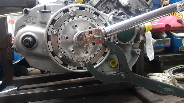 |
|
|
|
Post by Tobyjugs on Dec 11, 2021 17:56:27 GMT 1
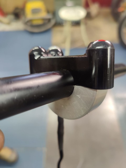
Am I right in thinking the sprocket nut is the same thread? Steve I'm not sure i knocked up a few titanium nuts for the 8 plate clutch i'm using clutch so this nut is redundant. After reading Marrcels last post i think i might have confused people. The clutch nut and sprocket nut are not the same on a YPVS i just checked. The nut below was made for the clutch side of the input shaft. This saves packing the nut out with extra washers.   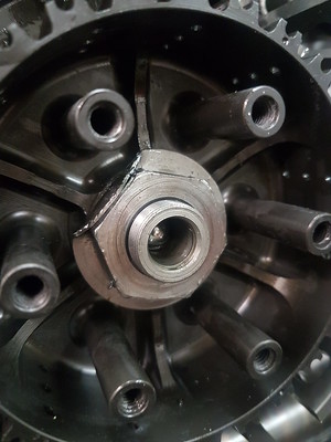 |
|


 If you click on the picture below you will see the video where the clutch siezed.


