|
|
Post by donkeychomp on Sept 3, 2022 21:31:18 GMT 1
They look SO good! More like art than a bike part. Nice one mate.
Alex
|
|
|
|
Post by dusty350 on Sept 16, 2022 21:23:39 GMT 1
|
|
|
|
Post by arrow on Sept 16, 2022 21:27:58 GMT 1
Never seen an LC head and barrels like that! Looks amazing.
We all know this doesn't affect the running, BUT, you know what a difference it makes when your driving with a polished windscreen. Same thing. Just great.
|
|
|
|
Post by dusty350 on Sept 16, 2022 21:46:23 GMT 1
Hi Gary  Just wanted to do something different to what I've done before - which is usually just vapour blasted. I hope to get some new mops at Kempton next week as mine are well past their best, and I might give them one more go before fitting. I know I wont get a great finish all over as my set up is very much DIY, but I think they will look ok once fitted with the black head, plus the side cases will be black cerakoted to contrast. I think oeb built an Lc with highly polished barrels/head and cases, and it looked great, but I would be there forever if I tried to do the same with my old bench grinder set up  There use to be a pro polisher near me but he disappeared years ago. He always looked like a coal miner - covered in greasy crap from the polishing process - I wouldn't think it was good for his health as he must have breathed a fair amount in over the years  So it's down to me, but it's not a job I relish  . Dusty  |
|
|
|
Post by mouse on Sept 17, 2022 6:45:54 GMT 1
As others have said, head and barrels look top notch, really love the cerakote finish, i think it is the best paint type option on engine parts. She is going to look lovely!
Mouse
|
|
|
|
Post by dusty350 on Sept 17, 2022 9:14:44 GMT 1
Hi mate, Yea, big thumbs up for Cerakote. This is the "H" type paint he has used, so baked in the oven, although I have had the air dry finish on the 400e, and that was good too. It's impervious to all the fluids you'll find on a bike, and a blow torch wont touch it either. It is a thin finish, as you know, so surface condition is a big factor if it's gonna look good. I had a shallow gouge on one of the barrels so started to polish it out thinking they would get cerakoted, but once I started on the polishing, I sort of got carried away !!  Dusty  |
|
|
|
Post by yamark on Sept 18, 2022 16:50:52 GMT 1
I missed the post on the barrels and head, you must have been covered in black crap after polishing for so long.
Looking ace as usual mate
|
|
|
|
Post by dusty350 on Sept 29, 2022 21:20:44 GMT 1
Time to rebuild the clutch basket after stripping it down. I bought a new billet Mitaka basket from Norbo;  20220929_201221 20220929_201221 by dusty miller, on Flickr If you remember from the strip down pics, the red gasket that sits between the basket and the gear was virtually non existent after 40 odd years of hard work. I remembered forum member "Rolie" had gone to great lengths to get some new gaskets made, as you cant buy them from Yamaha - they only sell the clutch as a complete unit. Rolie had sourced a modern alternative material that would withstand the rotational wear between the basket and the gear, and then had the gaskets reproduced. A message to Rolie found he still had just 2 left, which he very kindly sent to me for the rebuild. What a top guy - thanks so much  With the basket face down, the gasket sits on next;  20220929_201306 20220929_201306 by dusty miller, on Flickr 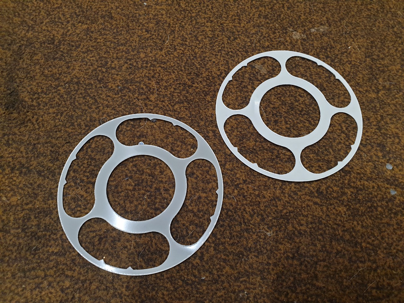 20220929_201327 20220929_201327 by dusty miller, on Flickr  20220929_201347 20220929_201347 by dusty miller, on Flickr Next, the driven gear is placed on top;  20220929_201418 20220929_201418 by dusty miller, on Flickr The 8 new damper pucs; 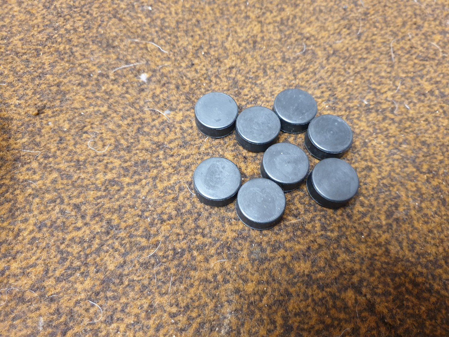 20220929_201441 20220929_201441 by dusty miller, on Flickr Pushed into place;  20220929_201526 20220929_201526 by dusty miller, on Flickr Then the original rubber pips;  20220929_201635 20220929_201635 by dusty miller, on Flickr 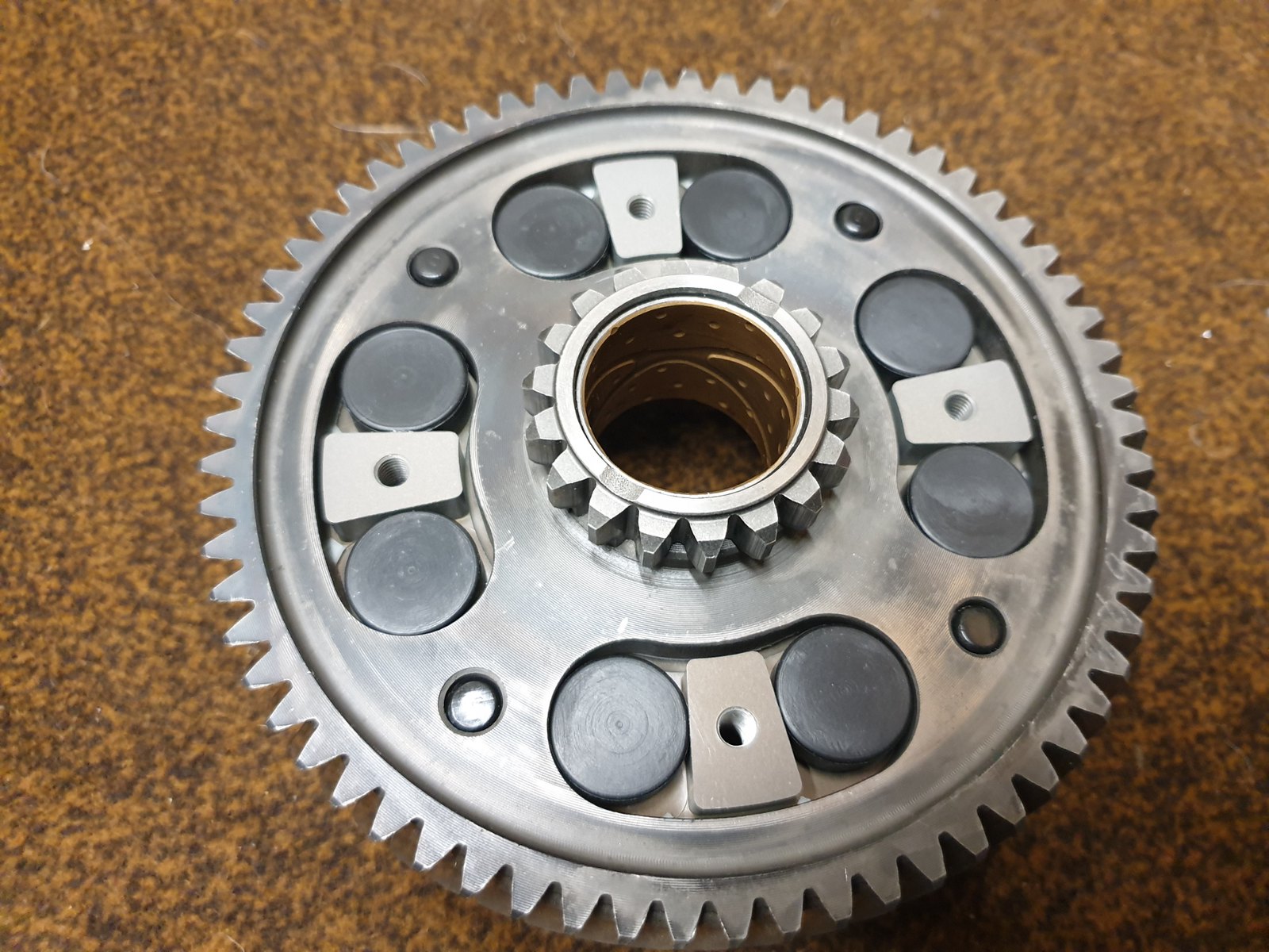 20220929_201710 20220929_201710 by dusty miller, on Flickr The hardened back plate can now sit on top;  20220929_201728 20220929_201728 by dusty miller, on Flickr The original set up had rivetts to hold it all in place, but the Mitaka basket is threaded for screws;  20220929_203209 20220929_203209 by dusty miller, on Flickr Some loctite is applied to the screws, and then they are tightened up. Last job is to fit the original rubber ring by stretching it over the basket "fingers";  20220929_203848 20220929_203848 by dusty miller, on Flickr  20220929_204101 20220929_204101 by dusty miller, on Flickr Ad that's the basket rebuilt  Dusty  |
|
|
|
Post by donkeychomp on Sept 29, 2022 21:41:01 GMT 1
Well, that's one part of an engine rebuild I could do! Neat and tidy mate.
Alex
|
|
|
|
Post by dusty350 on Sept 29, 2022 22:00:00 GMT 1
Easy peasy mate  Drilling the old rivetts out is the most time consuming part  Dusty  |
|
|
|
Post by donkeychomp on Sept 29, 2022 22:41:51 GMT 1
Oh I'm good at that...currently removing a load of them from the Spit!
Alex
|
|
|
|
Post by dusty350 on Oct 4, 2022 7:32:24 GMT 1
Time to fit the primary gear and rebuilt clutch basket. I fit the primary first gently pushing it into the crank seal aided by a little red rubber grease and some fresh oil. Line the grooves up for the new keyway;  20221003_195436 20221003_195436 by dusty miller, on Flickr I coat the keyway with some 3bond as they have been known to leak from here on pressure tests, and push the keyway in. Next is the smaller gear, which isn't keyed in any way, so just butts up against the primary gear. A new Belville washer;  20221003_195918 20221003_195918 by dusty miller, on Flickr Fitted with the dished edge towards the nut;  20221003_195946 20221003_195946 by dusty miller, on Flickr And finally the nut. torqued to 47ft/lbs. Next, the basket can slide on, remembering that I have already fitted the first thrust washer. You may need to rotate to idler gear slightly to get it to seat fully home. The next thrust washer can now slide on;  20221003_200426 20221003_200426 by dusty miller, on Flickr And then the clutch hub can be fitted. A new lock washer locates with a cut out in the hub;  20221003_201047 20221003_201047 by dusty miller, on Flickr  20221003_201109 20221003_201109 by dusty miller, on Flickr And then fit the nut and torque to 47ft/lbs again; 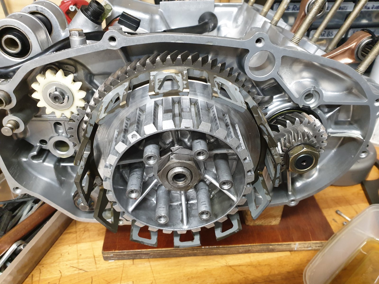 20221004_072829 20221004_072829 by dusty miller, on Flickr Clutch pack next. Dusty  |
|
|
|
Post by shaunthe2nd on Oct 4, 2022 8:36:20 GMT 1
Good progress and thread Dusty.
Will be interested in your build cost when you are done.
The bill for my current 250LC engine build is running at £997. and the 31k I did before that was £1028.
|
|
|
|
Post by arrdy350 on Oct 4, 2022 10:28:20 GMT 1
What did you use to lock the crank to do up the primary gear Dusty?
|
|
|
|
Post by dusty350 on Oct 4, 2022 17:38:34 GMT 1
Hi Shaun, I'm going to produce a list at the end of the build with all the current prices, and the prices from 4 years back when I did the last Lc build, as a comparison. Virtually every part has seen an increase of course, with a head gasket costing over 8 quid more this year than 2018 !!. Current prices are what's important of course, but I thought the comparison would make interesting reading. This build is gonna be my most expensive yet, but dont forget I had the cylinders resleeved back to standard from 2.25 over, plus a new crank, so that's a grand to start with. Pattern parts will be cheaper in most cases of course, but I always use Yamaha when available, so the comparison will be "like for like". Ardy, sorry, forgot to add a pic for locking the primaries. I use a small off cut of 15mm copper pipe, hammered flat at the end;  20221004_163947 20221004_163947 by dusty miller, on Flickr The gear teeth wont be damaged as the copper is much softer. You can also use rag, or the old favourite of a 2p coin, provided it's pre 1992, when it had a higher copper content than it does now. Lock the clutch hub and basket with a proper clutch holding tool to save damaging the basket  Dusty  |
|
|
|
Post by arrdy350 on Oct 4, 2022 20:51:19 GMT 1
👍
The mate who is helping me has a clutch tool. I will get a bit of copper pipe from work.
|
|
|
|
Post by dusty350 on Oct 7, 2022 21:10:01 GMT 1
I bought 2 litres of Silkolene light gear oil off the net, and soaked the EBC frictions for 24 hours;  20221006_213601 20221006_213601 by dusty miller, on Flickr And then hung them up to drain off the excess oil;  20221007_170245 20221007_170245 by dusty miller, on Flickr Hope to build the clutch tomorrow  Dusty  |
|
|
|
Post by dusty350 on Oct 8, 2022 20:20:00 GMT 1
Time to build the clutch. I'm not using the damper rubber rings, so it's just a case of frictions and steels. There are 7 frictions and 6 steels, so you start with a friction plate;  20221008_090705 20221008_090705 by dusty miller, on Flickr And then a steel. The steels have a flatter edge machined into them; 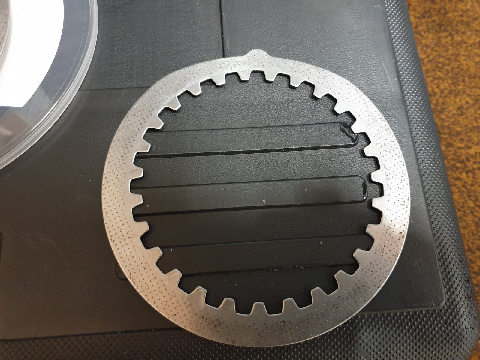 20221008_090737 20221008_090737 by dusty miller, on Flickr When evenly spaced around the basket, the plates shape help balance out any vibes when the clutch is spinning. I fit the first steel with the flat at the 12 o clock position;  20221008_090802 20221008_090802 by dusty miller, on Flickr The inner hub also has a circular mark - that too is positioned at 12 o clock. Add a friction plate, and then the next steel is at 2 o clock;  20221008_090926 20221008_090926 by dusty miller, on Flickr Friction plate, and then the next steel at 4 o clock;  20221008_091006 20221008_091006 by dusty miller, on Flickr Friction again, then a steel at 6 o clock, friction then steel at 8 o clock and then friction and the last steel at 10 o clock;  20221008_091300 20221008_091300 by dusty miller, on Flickr Then the last friction to finish the pack. A new pushrod ball can now be fitted;  20221008_092423 20221008_092423 by dusty miller, on Flickr  20221008_092512 20221008_092512 by dusty miller, on Flickr Followed by the "mushroom";  20221008_092528 20221008_092528 by dusty miller, on Flickr Pressure plate can now go on, with an arrow matching the inner boss mark at 12 o clock;  20221008_092944 20221008_092944 by dusty miller, on Flickr I bought 6 new standard clutch springs from Fowlers, which are plenty good enough for a standard engine, and should keep the easy clutch lever action;  20221008_093040 20221008_093040 by dusty miller, on Flickr  20221008_093316 20221008_093316 by dusty miller, on Flickr Then add the bolts, and tighten gradually and alternately, so 1, 3, 5, 2, 4, 6, The clutch is now finished. Next, spin the engine round to fit the pushrod;  20221008_090405 20221008_090405 by dusty miller, on Flickr Some red rubber grease on the seal lip, and it slides in;  20221008_090610 20221008_090610 by dusty miller, on Flickr Dusty  |
|
|
|
Post by donkeychomp on Oct 8, 2022 22:02:20 GMT 1
I have actually done that before (with I believe your help).
Alex
|
|
|
|
Post by andyr46 on Oct 9, 2022 15:50:44 GMT 1
Outstanding work, love the pics.
|
|
|
|
Post by dusty350 on Oct 10, 2022 8:18:51 GMT 1
Couple of components left now. The kickstart assembly has been cleaned and is ready to go in. There is a stopper - marked in red, that will sit against the casting in the casing;  20221008_094948 20221008_094948 by dusty miller, on Flickr  20221008_095000 20221008_095000 by dusty miller, on Flickr The other part that needs locating as you fit the assembly is the spring on the back - this fits into the horseshoe shaped casting on the case;  20221008_095332 20221008_095332 by dusty miller, on Flickr  20221008_095513 20221008_095513 by dusty miller, on Flickr Once the assembly is in place, the last job is to hook the large spring, clockwise, up to the post at the top of the case;  20221008_095742 20221008_095742 by dusty miller, on Flickr Kickstart done. You can fit a kickstart at this point and carefully rotate to check operation if you wish. Water pipe is aluminium, and easily marked. A previous owner must have used a screwdrver or bladed tool to ease a hose off, as mine was a bit scarred. I polished the worst out, but looking through my engine parts stash for a different part, I found a better one;  20221008_095922 20221008_095922 by dusty miller, on Flickr New retaining clip and "O" ring;  20221008_100246 20221008_100246 by dusty miller, on Flickr And in place, with some red grease on the "O" ring;  20221008_100623 20221008_100623 by dusty miller, on Flickr And that's the clutch side done. Nothing difficult, and just a couple of specialist tools needed - clutch holding tool and a torque wrench really;  20221008_100803 20221008_100803 by dusty miller, on Flickr Spin the engine round, and fit the rotor, making sure the groove in the rotor's central boss sits over the woodruff key on the crank. Add plain and spring washers, and then tighten the main nut, holding the rotor with a rotor locking tool. I didn't polish this rotor as it was corrosion free;  20221008_215624 20221008_215624 by dusty miller, on Flickr  20221008_221208 20221008_221208 by dusty miller, on Flickr Once the nut is torqued to 61ft/lb, I draw some lines on the nut so It will be easy to see if there is any loosening on initial running;  20221008_221208 20221008_221208 by dusty miller, on Flickr Timing will be checked once the top end is on. Next task will be stripping the clutch case and getting it Cerakoted to match the cylinder head, then rebuild the water pump and oil pump  Dusty  |
|
|
|
Post by JonW on Oct 13, 2022 0:41:34 GMT 1
Super efforts on not only the rebuild, but on documenting it so fully. Dusty 'Haynes' Miller... or maybe we just all need the new 'Miller Manual', available in all good bookshops just in time for Christmas....   |
|
|
|
Post by donkeychomp on Oct 13, 2022 21:41:51 GMT 1
To be honest Haynes need to use people like Dusty instead of the oily fingered idiots they usually employ...I would happily buy a copy of a Dusty Manual (if he signed it that is...)
Alex
|
|
|
|
Post by dusty350 on Oct 20, 2022 20:01:27 GMT 1
Built the pistons up last night;  20221019_185131 20221019_185131 by dusty miller, on Flickr Fitted the rings to each piston, and a circlip on each, so right side piston has got the inner circlip fitted on it's left side, and vice versa. Today I fitted them. Some silicon hose, cut down the middle, sits over the studs to prevent any damage to the piston and rings, and the piston wont move around so much when you fit the remaining circlips. Some clean rag around the bottom of both pistons to stop a dropped circlip ending up underneath the crank too ! Little ends get an oil bath first;  20221020_172556 20221020_172556 by dusty miller, on Flickr Then fit to the rod eye;  20221020_170722 20221020_170722 by dusty miller, on Flickr New gudgeon pins get some oil, as do the parts of the piston the gudgeon pin sits in, then they just push in;  20221020_171255 20221020_171255 by dusty miller, on Flickr Then the outer circlips on both pistons. I find it easiest to fit the circlips with the open ends in the cut out on the piston. Once in the groove, I rotate the circlip in the groove, so the open ends are away from the cut out;  20221020_173818 20221020_173818 by dusty miller, on Flickr Dusty  |
|
|
|
Post by dusty350 on Oct 20, 2022 21:35:15 GMT 1
Picked up my clutch case from Jamie tonight. When I bought the Fzrd, the 350 engine had a Pv clutch case fitted, and I was keen to fit a correct Lc case, so used the one from the 250 Lc. It was pretty good, and free from rash, but was cosmetically challenged after 40 odd years;  thumbnail (7) thumbnail (7) by dusty miller, on Flickr I used to get side cases powdercoated, but it's not normally petrol safe, so nowadays it's Cerakote that gets my vote. I wanted a finish a bit less than a satin, mainly because my barrels are polished, as well as the centre disc and some other small parts, and thought it would offer a better contrast. Jamie vapour blasted it all, then masked it up and applied Graphite black, H series Cerakote. The main case was baked for an hour at 148 degrees, and the oil pump cover, being plastic, got 2 hours at 75 degrees;  20221020_195854 20221020_195854 by dusty miller, on Flickr  20221020_195904 20221020_195904 by dusty miller, on Flickr The centre disc on the Lc has a bit of rubber tube that helps to dampen noise/vibes from the clutch. I'm gonna fit the later, bigger damper from a Pv;  20221020_195918 20221020_195918 by dusty miller, on Flickr The centre disc is an aftermarket "Yamaha" alloy disc that came in a box of spares with the Fzrd. It looked unused, but the silver anodised finish looked tired. I polished it off on my buffing wheel - took ages, but came up nice. I will post a pic once it's fitted  Dusty  |
|
|
|
Post by donkeychomp on Oct 20, 2022 22:19:11 GMT 1
That looks so cool! He's a talented chap for sure.
Alex
|
|
|
|
Post by dusty350 on Oct 23, 2022 19:14:10 GMT 1
Time for the top end now. New gaskets from Yamaha - bought some time back, but current price is £8.53 each from Fowlers;  20221023_095626 20221023_095626 by dusty miller, on Flickr Now, each to their own, but I always apply a thin smear of 3 bond to the base gaskets. The vapour blasting process showed up a couple of small nics in the surface that the gaskets sit upon, so maybe not necessary, but my ocd says do it !! It's always fiddly getting the barrels on if you are on your own. I usually employ one of the kids, but they've both left home now and the missus was at the Gym, so I needed to make life easier. I used some silicon tube - fitted to the studs allowing the barrel to sit on the silicon, whilst I compressed the rings and eased the pistons up into the lightly oil bore;  20221023_103008 20221023_103008 by dusty miller, on Flickr Not exactly an action shot, but I didn't have a spare hand to take the pic !! Anyway, the tubing keeps the barrel sat at a height where you can ease the piston up and into the barrel rather than lowering the barrel down onto the piston. I found it a lot easier this way. Once the piston is in the bore, I apply a little bond, and sit the barrel down into place. A new head gasket from Yamaha is currently £58.34;  20221023_095701 20221023_095701 by dusty miller, on Flickr I dont add sealant to this, just sit it on the barrels, and put 2 head bolts through the head to help keep the gasket in place, then seat the head and add the rest of the bolts;  20221023_112341 20221023_112341 by dusty miller, on Flickr Torque the bolts up to 17ft/lbs. I polished up the temp sender and tightened that up too. Just need 2 new plugs, and then it's reedblocks.  20221023_112313 20221023_112313 by dusty miller, on Flickr Dusty  |
|
|
|
Post by jessy03 on Oct 23, 2022 20:13:23 GMT 1
Pukka job Dusty 👍👍👍
|
|
|
|
Post by dusty350 on Oct 23, 2022 21:19:42 GMT 1
Thanks Jess  I normally buy silicon hoses for my engine builds, usually coz the ones I have are either scabby, or missing altogether. I've got some mint, original hoses with clips, so rather than keep spending money, I thought I would fit them to this build;  20221023_193017 20221023_193017 by dusty miller, on Flickr  20221023_192948 20221023_192948 by dusty miller, on Flickr I fit this hose before I fit the reedblocks as you have a bit more room to wriggle it into place. A thin smear of red rubber grease inside each end of the hose makes fitting a lot easier. Once in place and the clips tightened, you can fit the reedblocks. New gaskets;  20221023_095621 20221023_095621 by dusty miller, on Flickr £2.86 each currently. I always apply some 3 bond to each side of these gaskets. The inlets are often the culprit for air leaks, so I always add sealant to this area. New inlet rubbers from Norbo, and stainless cap heads;  20221023_195941 20221023_195941 by dusty miller, on Flickr Once I fitted both sides, I fit the cross over tube, which I polished up a bit, and use new clips, as this engine didn't have any fitted when I got it;  20221023_202503 20221023_202503 by dusty miller, on Flickr I had to apply a little red grease to the ends of the tube as it was really tight getting them into the rubbers. Hopefully they will be leak free now; 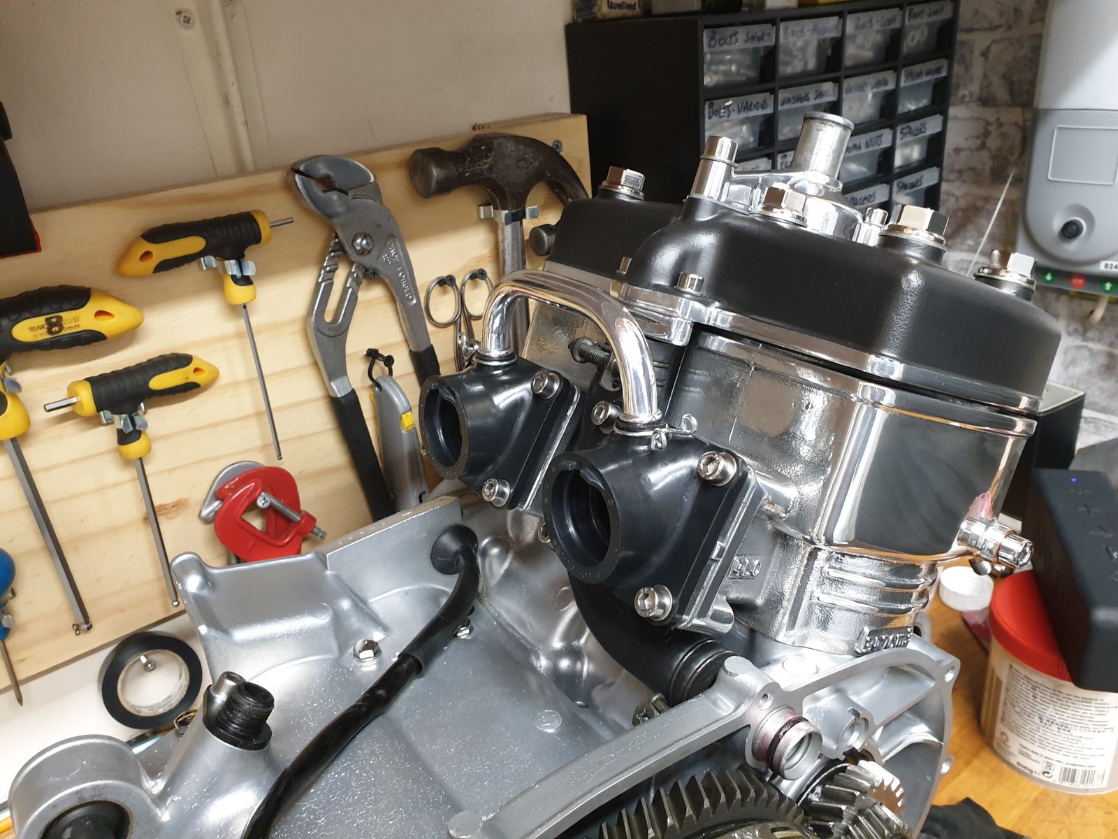 20221023_203424 20221023_203424 by dusty miller, on Flickr Next ob will be to build up the clutch case with the water and oil pump, then that can be bolted on. Dusty  |
|
|
|
Post by dusty350 on Oct 26, 2022 22:10:46 GMT 1
I started on the clutch case tonight. First to fit was the water pump seal and bearing;  20221026_195408 20221026_195408 by dusty miller, on Flickr Seal is £25.69, and the bearing is £14.69. The seal has a handy reminder in case you forget which way in it goes !!;  20221026_195821 20221026_195821 by dusty miller, on Flickr I apply red grease to the seal and the housing it sits in;  20221026_200010 20221026_200010 by dusty miller, on Flickr You can start pushing it in but it starts to get tight, so I use a bolt and washers, and a nut, and tighten the nut so the seal gets drawn into it's housing with a nice even pressure from the washer, which is exactly the same size;  20221026_200058 20221026_200058 by dusty miller, on Flickr  20221026_201527 20221026_201527 by dusty miller, on Flickr  20221026_200650 20221026_200650 by dusty miller, on Flickr Once the seal is seated, I do the same process with the bearing;  20221026_200855 20221026_200855 by dusty miller, on Flickr The bearing does sit slightly proud of it's housing. Next push the pump impellor in from the outside, and fit the pin;  20221026_203401 20221026_203401 by dusty miller, on Flickr  20221026_203633 20221026_203633 by dusty miller, on Flickr Then the cog, washer, and new circlip;  20221026_203701 20221026_203701 by dusty miller, on Flickr  20221026_203723 20221026_203723 by dusty miller, on Flickr And that's the water pump done  Dusty  |
|