|
|
Post by stusco on Mar 11, 2017 23:27:23 GMT 1
The rubbers are sealed with bungs so the reeds are not tested
|
|
|
|
Post by dusty350 on Mar 12, 2017 9:20:40 GMT 1
Morning Tony I've used a low melting point grease - the thinnest smear to seat the seals, so hopefully it will be fine. I've always used the same stuff and never had any issues. I always use red on brake seals though. There is not much left to do now. I need a silicon water pipe for the head to clutch casing, which I will get this week. Oil pump needs to go to Arrow but that can be fitted once the engine is back in the frame if needs be - the pump shaft and sprocket are already fitted so wont affect the final fitting of the clutch case. Forgot to mention I fitted a new Yam gasket for the water pump; 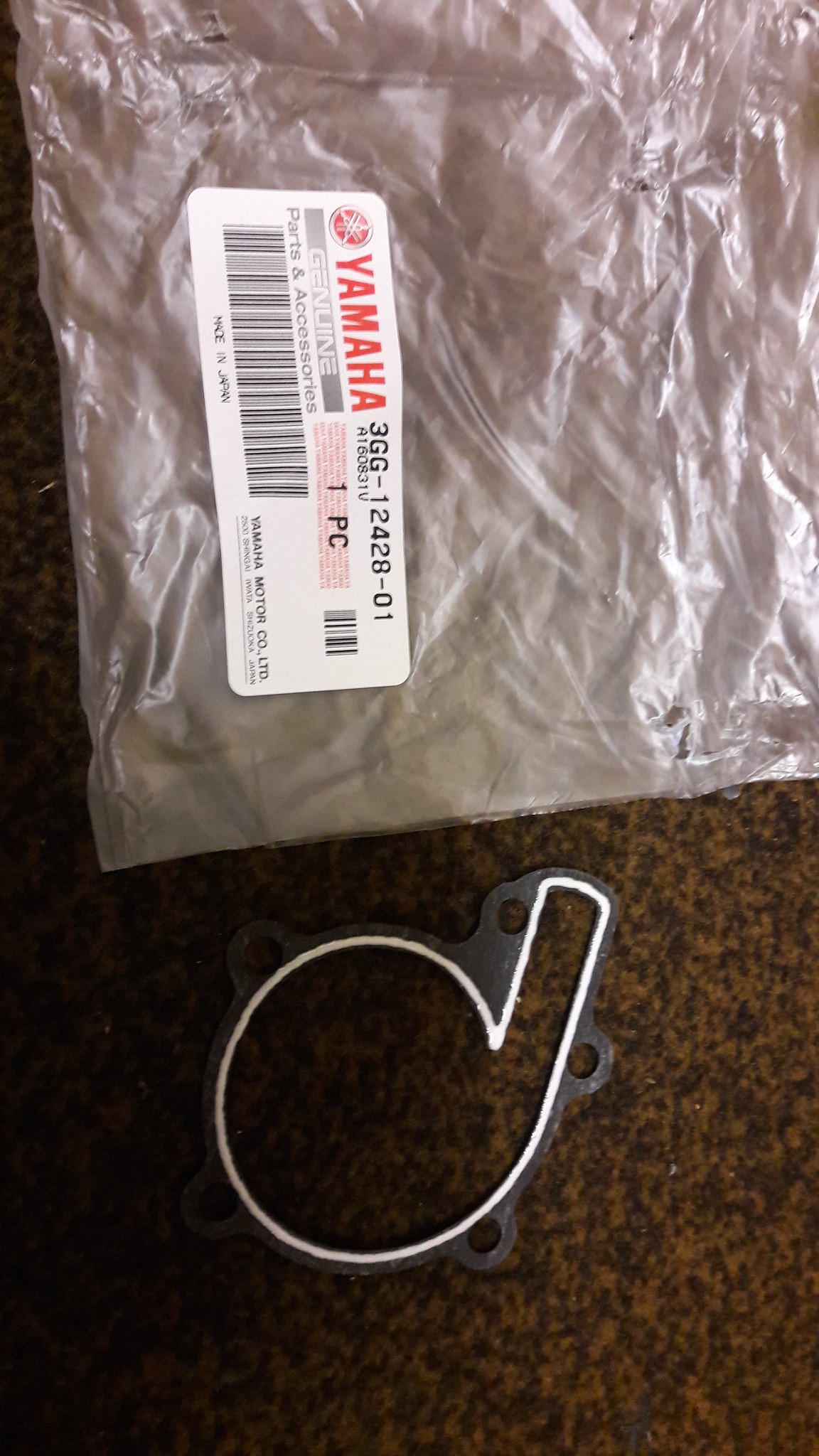 20170311_101955 20170311_101955 by David Miller, on Flickr I've cleaned up a kickstart, and stripped and cleaned the clutch rod actuator that bolts inside the left case - that was really manky and the ball bearing now rattles as it can move as it should. Need to sort the genny wiring too - a plug needs re attaching, and will do that with the engine on the bench coz it's easier ! Engine will need to be timed. I don't have much experience of that, but I know a very nice man that does, and he has a dial gauge, so I will post pics of the process when it happens. Dusty  |
|
|
|
Post by ibby4585 on Mar 12, 2017 9:43:58 GMT 1
That looks great Dusty, now if i take that motor off you and give you mine you can start again. :-)
|
|
|
|
Post by 4l04ever on Mar 14, 2017 15:46:36 GMT 1
Just adding as per in the Ibby4585 engine rebuild thread, that piston circlips are better with no tang or with the tang removed, as the tang can fatigue and cause damage when they fall off.
|
|
|
|
Post by yamark on Mar 15, 2017 21:52:20 GMT 1
The left side casing was missing the spacer in the gear shaft hole. After measuring I bought a needle roller bearing from Simply bearings to solve the problem. I wanted it to be a tight fit, and had to use my dremmel with a circular sanding attachment to remove some alloy from inside the hole. Doing it a little at a time so as to not make the hole too big - I managed to get the bearing in - a nice tight fit and aligned for the shaft to give support; 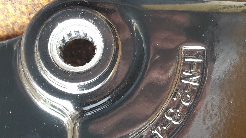 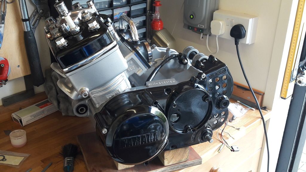 Dusty  I do like the needle roller bearing solution, should last "forever". The engine looks "top draw" Dusty, put together with surgical precision - well done mate 
|
|
|
|
Post by dusty350 on Mar 15, 2017 22:18:07 GMT 1
Hi Had a productive day today thanks to Mark - Yamark, coming over and doing a couple of vital bits to my engine  I don't posses a dial gauge, but Mark does and kindly offered to check the timing now it's all together. I had marked the stator plate before I dismantled the engine ages ago, and I lined my marks up when I bolted the stator back on, but obviously it needed checking. 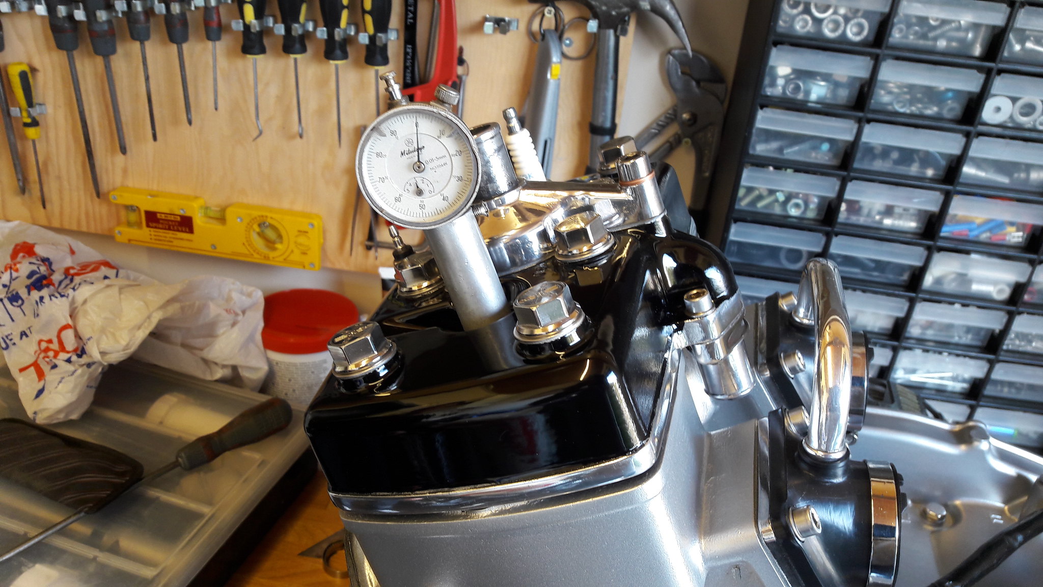 20170315_094549 20170315_094549 by David Miller, on Flickr This first pic shows the dial gauge fitted. Mark turned the flywheel to find top dead centre (tdc), and then zeroed the gauge. He then turned the rotor clockwise, and the needle did 2 complete revolutions of the dial - that's 2 degrees before tdc. We then checked the timing mark on the rotor; 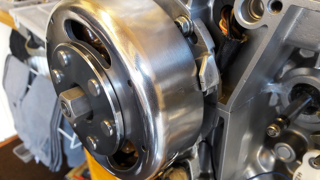 20170315_094631_zpsxjskzo4n 20170315_094631_zpsxjskzo4n by David Miller, on Flickr So, happy with that. If you look carefully you can see the pencil mark on the stator plate that I put there before strip down. It lines up with the crank case join, but still needed checking for accuracy. The other thing Mark kindly did was pressure test the engine. I had the blanks that I bought on this forum some time back, but never used them, plus I don't have a gauge to measure the pressure. So first job was to fit the exhaust port blanking plates; 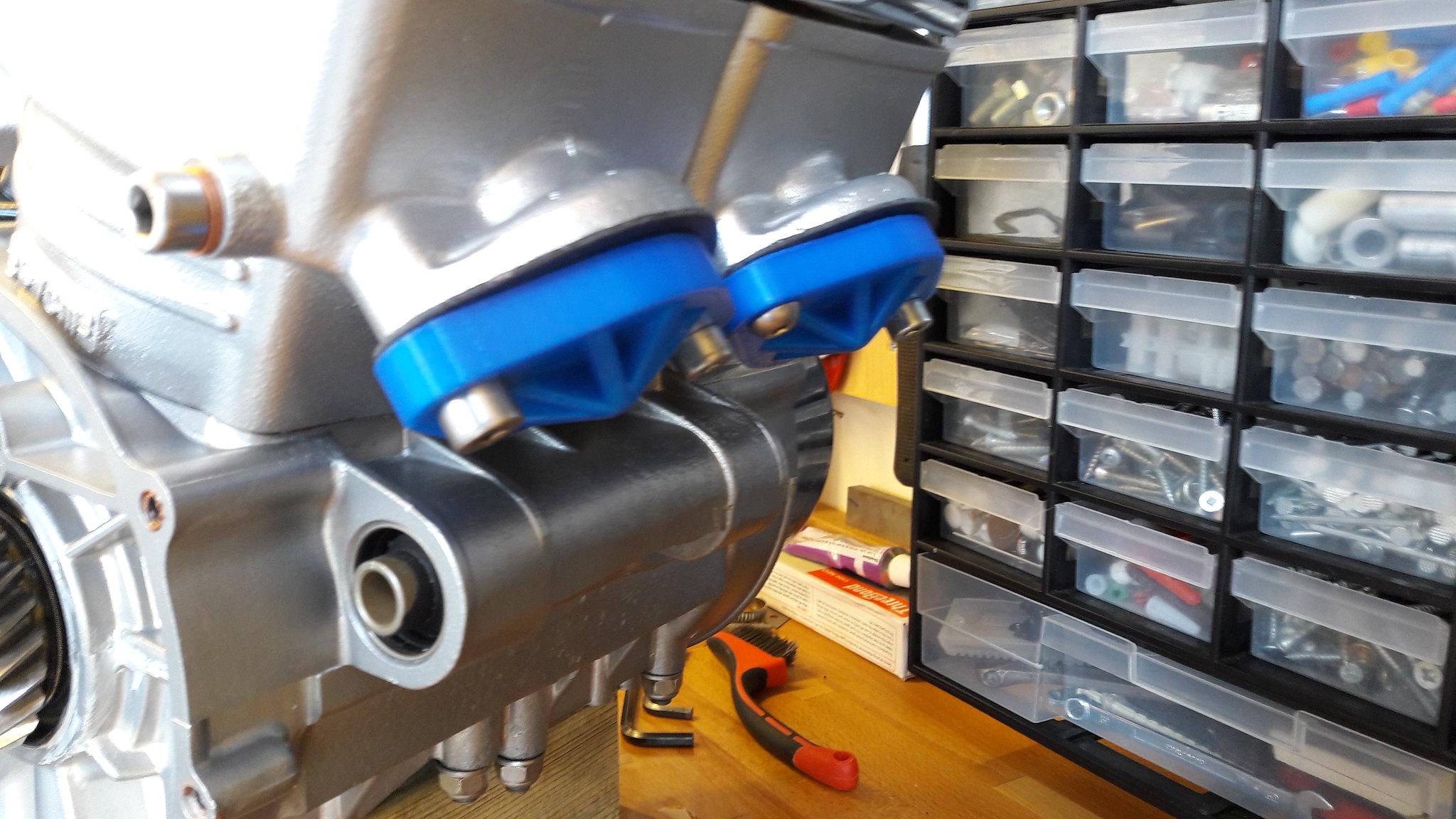 20170315_100650 20170315_100650 by David Miller, on Flickr And then the bungs for the carb inlets. Mark made up a blanking plug for one side of the carb rubbers, and the other side was where he attached his gauge - this is also where he attached the pump for pressurising the engine. He then charged the engine with about 6psi of air. Quite quickly we could see the gauge starting to drop - not good- so a bit of soapy water and a brush was employed to find the leak. Mark thought the crossover tube inlets were the culprit, and the soapy water proved him right: 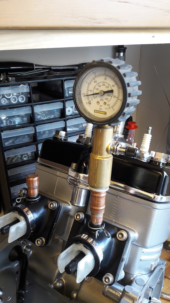 20170315_100644_zpso9haz4yz 20170315_100644_zpso9haz4yz by David Miller, on Flickr 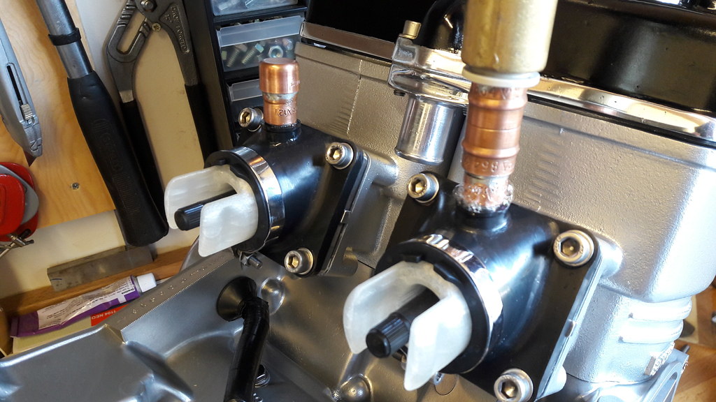 20170315_100438_zpsyp5qretb 20170315_100438_zpsyp5qretb by David Miller, on Flickr I hadn't fitted the wire clips - the rubbers are new and the fittings were a tight fit, but not tight enough obviously !. We fitted the clips and recharged the system- then brushed the joints with soapy water again and no bubbles !!. We went and had a brew and left the engine for 20 minutes, and I'm pleased to say the gauge didn't drop at all. So, happy with that. Goes to show, the clips may look like they don't do much on the balance tube but they made all the difference to holding pressure. So a massive thanks to Mark for spending time on his day off to both time and pressure test the engine for me  Cheers buddy  So now the engine can go back in the frame - I've got a silicon hose coming for the head to clutch case joint, so once that's fitted the engine will go in. Dusty  |
|
|
|
Post by ibby4585 on Mar 16, 2017 19:41:11 GMT 1
Thats great Dusty, great end to the build.
I look forward to it being fitted and hearing it run.
Kris
|
|
|
|
Post by yamark on Mar 16, 2017 21:16:56 GMT 1
The pictures do NOT do this engine justice, it is simply flawless. I think Dusty might be a bit "Borg" because of his pursuit for perfection!  (Only "trekies" will understand that)
Mark |
|
|
|
Post by dusty350 on Mar 16, 2017 22:58:59 GMT 1
Haha, when you said Borg, I thought you meant my eyes were too close together, like Bjorn !!  Thanks to Mark's final checks yesterday, today was the day the engine goes back into the frame. Lots of foam pipe lagging covering the frame tubes to protect them, and I lifted it straight in. Bolted it all up and then realised that I had forgotten to fit the 2 anti twist washers to the mounting points on the engine  Luckily I managed to fit them 1 at a time without taking the engine out again - just loosened off the frame mounting plates 1 at a time and wiggled the washers in. Tightening up the mounting bolts squeezed them onto the engine mounts so job done. The clutch case is on temporarily - it will come off for a final check and torqueing, and then the case gasket can be fitted. My silicon hose arrived today so I fitted that whilst the engine was on the bench. I ordered some exhaust crush washers today so they should come tomorrow. I will remove the chrome Allspeeds from the blue Hybrid and fit them onto this bike - I have a gorgeous pair of stainless TSA's that are going on the blue bike. Once the 'speeds are on I will refit the rad and plumb it in. I'd love to post the pic of the engine in the frame that I took tonight, but guess what ? Photof**ket is being a t**t again and wont even let me upload it so I will try again later   Dusty  |
|
|
|
Post by rostrumorhospital on Mar 17, 2017 17:51:21 GMT 1
Brilliant work Dusty, a great reference document for us all, really like the overall look you've picked for the engine with the alloy barrels and gloss black head & casings, looks trick but not too blingy, will be great to see it in the bike and running, your definately on the home straight now, just in time for spring.
Enjoy!
|
|
|
|
Post by dusty350 on Mar 17, 2017 22:03:39 GMT 1
Hi Cheers guys  Engine is now bolted up in the frame, so today I removed the chrome Allspeeds from the blue Hybrid so I could fit them to this bike. I bought 2 new crush washers from Fowlers;  20170317_125454_zpszf3u5kby 20170317_125454_zpszf3u5kby by David Miller, on Flickr I put a bead of clear silicon on the exhaust gaskets and these crush washers to try and help eliminate the oily dribbles you get from the cylinders. We will see if it works !. Then a bit of silicon on the Allspeed header and bolted it up with new stainless hex head bolts; 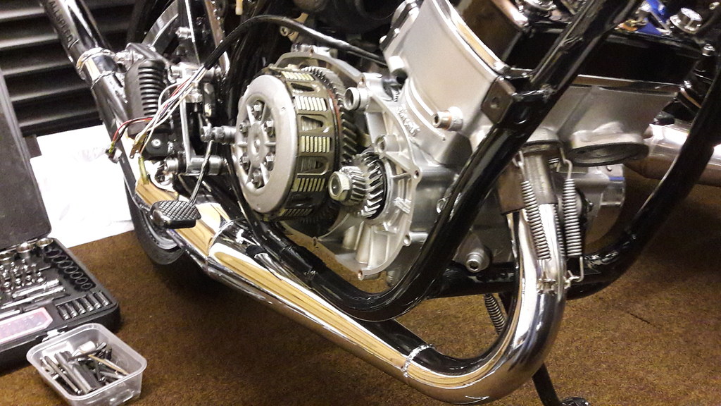 20170317_131715_zpsrl0nqxud 20170317_131715_zpsrl0nqxud by David Miller, on Flickr I think the Allspeeds look great on this build; 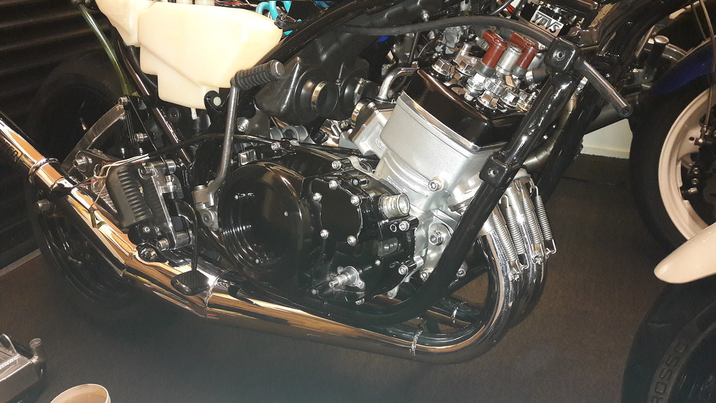 20170318_094737_zpsrdzixxex 20170318_094737_zpsrdzixxex by David Miller, on Flickr I double checked all fixings for torque,and fitted 2 new B8es plugs. I will refit the clutch case tomorrow with a new gasket; 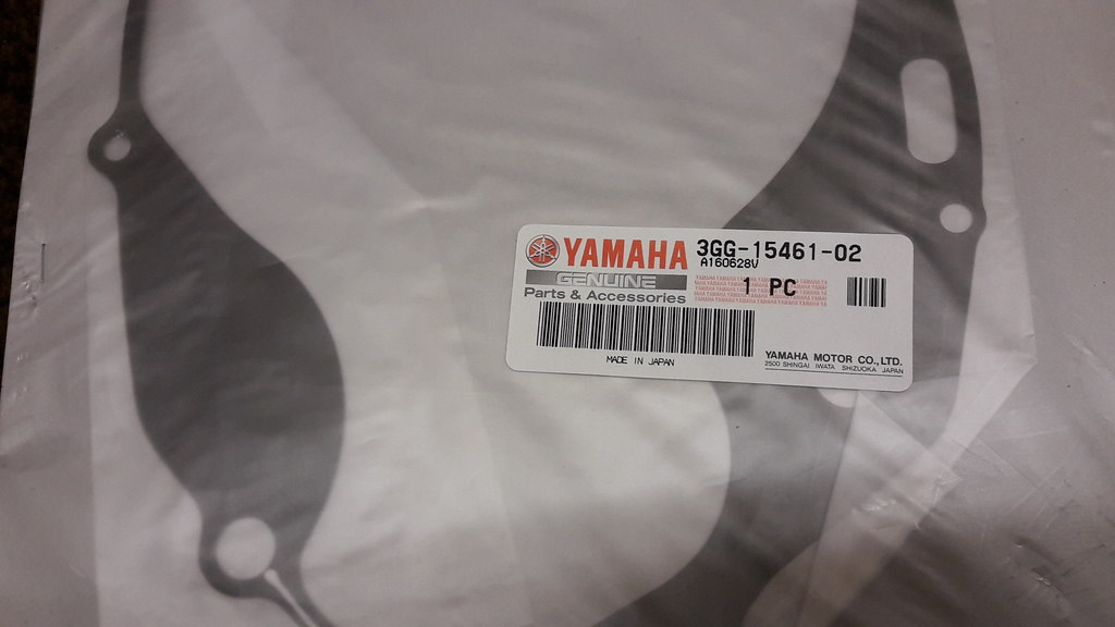 20170317_125507_zps3jjrkkp0 20170317_125507_zps3jjrkkp0 by David Miller, on Flickr Dusty  |
|
|
|
Post by ibby4585 on Mar 17, 2017 22:23:25 GMT 1
Lovely bikes Dusty they really are.
|
|
|
|
Post by arrow on Mar 17, 2017 22:32:08 GMT 1
Simply stunning work dusty.
|
|
|
|
Post by 350guy on Mar 17, 2017 22:33:34 GMT 1
This is pure work of art, dedication and attention to detail, simply amazing!
Guys like me can only dream of this top notch quality!
You the man Dusty!
Have a great weekend folks!
Cheers,
Daryl
|
|
|
|
Post by dusty350 on Mar 17, 2017 23:16:41 GMT 1
Hi Kind words fellas, thank you, but please understand I am no better at this than anyone else. If you take your time, spend money on the right parts and services and are methodical, anyone can build one of these engines. I can't emphasise enough what a simple engine they are. When you strip them down, bag the parts up in their own bags - keeps parts together, and when you feel like it you can clean/inspect/renew the contents of each bag. Lots of digital pics so you can refer back. Download a parts fiche - as well as part numbers it shows the order parts are assembled in - great as a cross reference. Use genuine parts where and when you can, if not use the best pattern parts you can afford, but genuine seals and gaskets are a must. Always replace circlips and "E" clips if they have been disturbed during the strip down. Use recommended suppliers for parts - Norbo, Martin Brown, PJME and Fowlers have supplied virtually everything for my builds, and all are dependable and enthusiastic about these bikes and the service they provide. Granby's - RIP - were awesome too for genuine parts but sadly no longer trading. And use this forum as your greatest resource of help and info - so many guys have been there and done it before and are happy to offer help and encouragement. The good thing about rebuilding these engines is there is a healthy stock of most engine consumables still available - bearings, seals, gaskets, O rings can all be sourced easily enough. And when you find parts nla, there are good patterns available. So I would happily encourage anyone to have a go at a rebuild, take their time and enjoy it - coz their is bugger-all on the telly !! Dusty  |
|
|
|
Post by dusty350 on Mar 18, 2017 12:50:38 GMT 1
Bit more done this morning. The balance pipe clips were fitted today - the leak down test showed how necessary they are !! 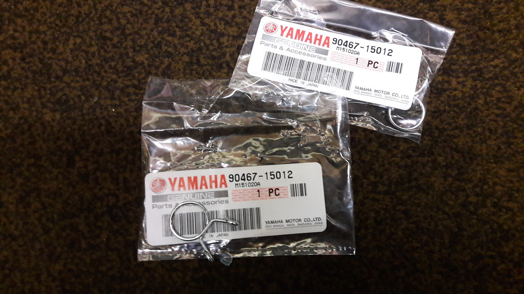 20170318_090332_zpsgwvah5xe 20170318_090332_zpsgwvah5xe by David Miller, on Flickr The clutch case gasket went on, and then the case itself; 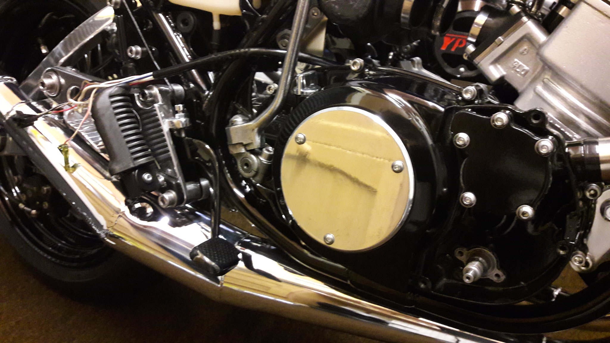 20170318_111351 20170318_111351 by David Miller, on Flickr Then the rad and the new silicon hoses were fitted - hoses had to be trimmed a bit as they were slightly too long, but easy enough with a sharp knife. The ally disc was found in a box of spares that came with a bike ages ago. Wasn't sure whether to use it or not but it does look good I think. It needs some time on my polishing wheel though to remove some scratches. I can start adding some cables next, and I'm using the 31k carbs that are on the blue bike, so will liberate those at some point, check them over and fit to this engine. Dusty  |
|
|
|
Post by ojay on Mar 18, 2017 23:06:56 GMT 1
Dusty this engine, bike look the absolute dogs 👍👍 please let me know if you ever want to sell any of your builds ? Cheers OJ
|
|
|
|
Post by dusty350 on Mar 19, 2017 9:27:05 GMT 1
Hi Oj Yea, will do mate. They get moved on more often these days !! I can now check for chain alignment - the bike came with sprockets fitted but no chain so not sure if the offset that is fitted is correct. I've got a straight edge that I will place against the sprockets to check. I want to get a kickstart repair kit from Norbo - the original kickstart that I cleaned up is a little "baggy" ! Need to get a few other small parts and wire it up and then it will be nearly done  Dusty  |
|
|
|
Post by ibby4585 on Mar 19, 2017 10:59:44 GMT 1
Hi Dusty.
Can i ask what rad that is please? Is it larger and does it cool better?
Thanks
Kris
|
|
|
|
Post by jon on Mar 19, 2017 11:33:00 GMT 1
Dusty, I know you welcome comments on this thread, so would just like to say something.
When you said you did the flywheel nut up as folllows: 'I did the nut up by locking the clutch and primary gears with my bit of flattened copper pipe which works a treat.' might I suggest this is not the best way.
IMO any possibility of twisting the crank should be avoided. Now I know the torque involved is fairly low to do this, and that if you managed to twist a crank in this way it would probably fail in use anyway; but a bit like the tang debate, why take the risk?
Jon
|
|
|
|
Post by stusco on Mar 19, 2017 16:37:09 GMT 1
I made a tool from flat bar from b&q ,it's like scissors with bolts for pegs that fit in the holes in the flywheel easy peasy
|
|
|
|
Post by mouse on Mar 19, 2017 18:22:28 GMT 1
Work of art Dusty, both of them!
The Allspeeds look just right on the white one. I love the white paint set you should feel really proud, they really are fantastic
Mouse
|
|
|
|
Post by dusty350 on Mar 19, 2017 21:08:48 GMT 1
Hi Andrew, Cheers mate, I'm pleased with how it's coming together now  Hi Jon, fair comment mate. I managed to get the nut fairly tight without the copper, bit did a final nip up of both the rotor nut and primary drive nut - I didn't go mad as I know it can be dodgy. Hi Kris, the rad is one of the Chinese rads, I presume from ebay. It was on the bike, unused, when I bought it, so it remains to be seen how good it is. Dusty  |
|
|
|
Post by vic6169 on Mar 29, 2017 14:03:48 GMT 1
Dusty
Just read this front to back and its an awesome thread, awesome build and really helps people like me who haven't built an LC engine in 30 years and now have 2 engines to do (previous dodgy owners).
Attention to detail is stunning. Looking forward to finding out how she runs mate.
All the best
Vic
p.s. if you ever sell your bikes PM me.
|
|
|
|
Post by dusty350 on Mar 29, 2017 15:52:45 GMT 1
Hi Vic Thanks mate. It was always meant to be my version of a build - certainly not definitive, and I appreciate there is always other ways of doing it, and I hope whoever uses it as a guide benefits from all the contributions made by other forum members too. I have no engineering background, and no access to specialist equipment, so I hope it encourages guys that have never done it to have a go themselves, because this thread hopefully shows that anyone can achieve it with time/patience and money of course !! They really are a very simple engine to assemble. Dusty  |
|
|
|
Post by richclare on Apr 16, 2017 9:56:46 GMT 1
To remove the bearing on the selector drum means removing the cross head screw first. I've never had one yet that's come out easily so I drill the head off, remove the cup washer and star head, which just pulls off, and then you can get some grips on the bolts shank and that usually turns out quite easily. Ignore the bolt in the pic, it's the new one; 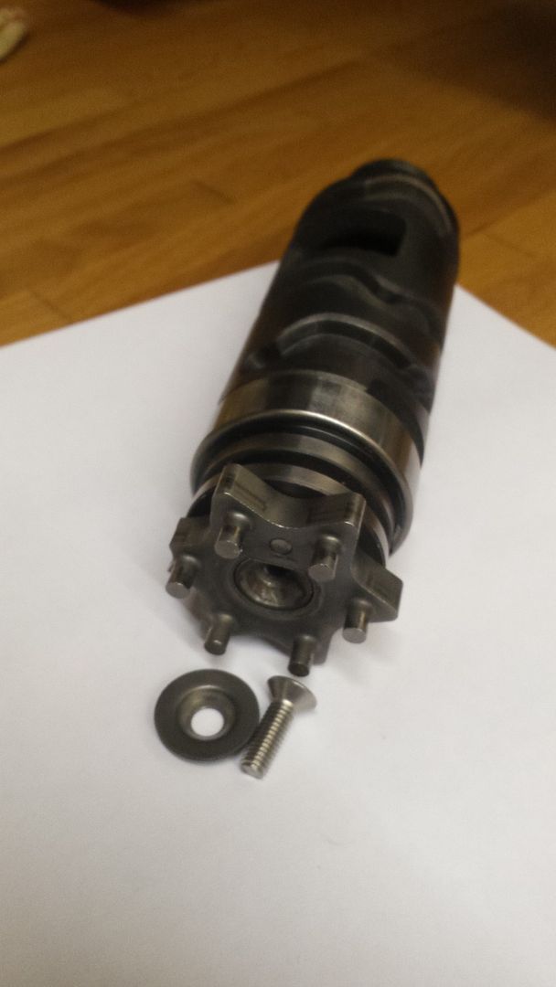 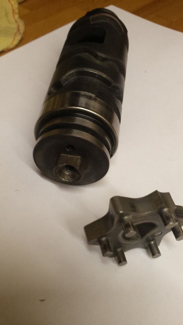 Once the star head is off you face a fiddly circlip, located directly above the bearing; 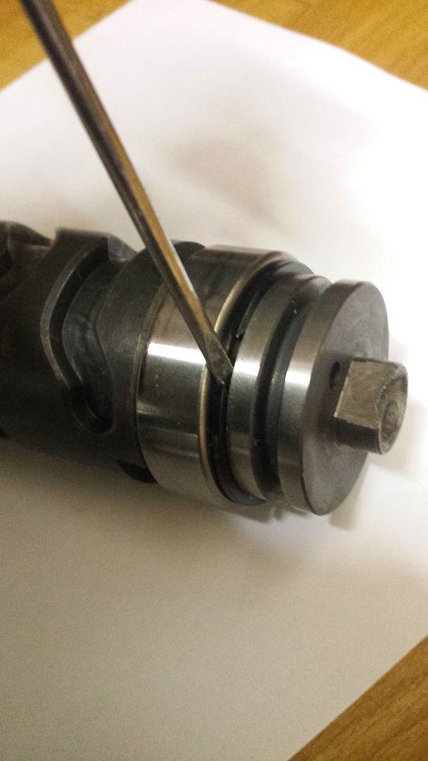 I gently prise it up with a small screwdriver. Once off the bearing just lifts off. I check the surface the bearing rotates on is in good nic and then it's a case replacing with new parts; 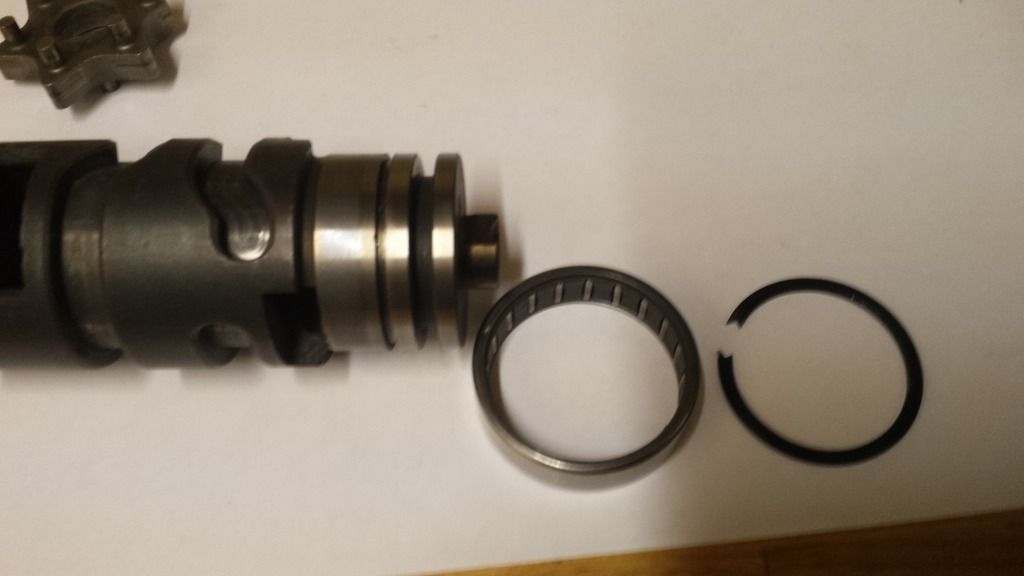 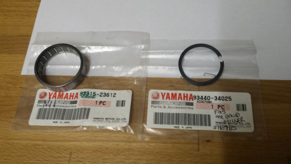 I submerge the new bearing in fresh gear oil before fitting. Worth checking the other end of the drum to make sure the brass plunger that makes contact for the neutral switch works properly by springing in and out; 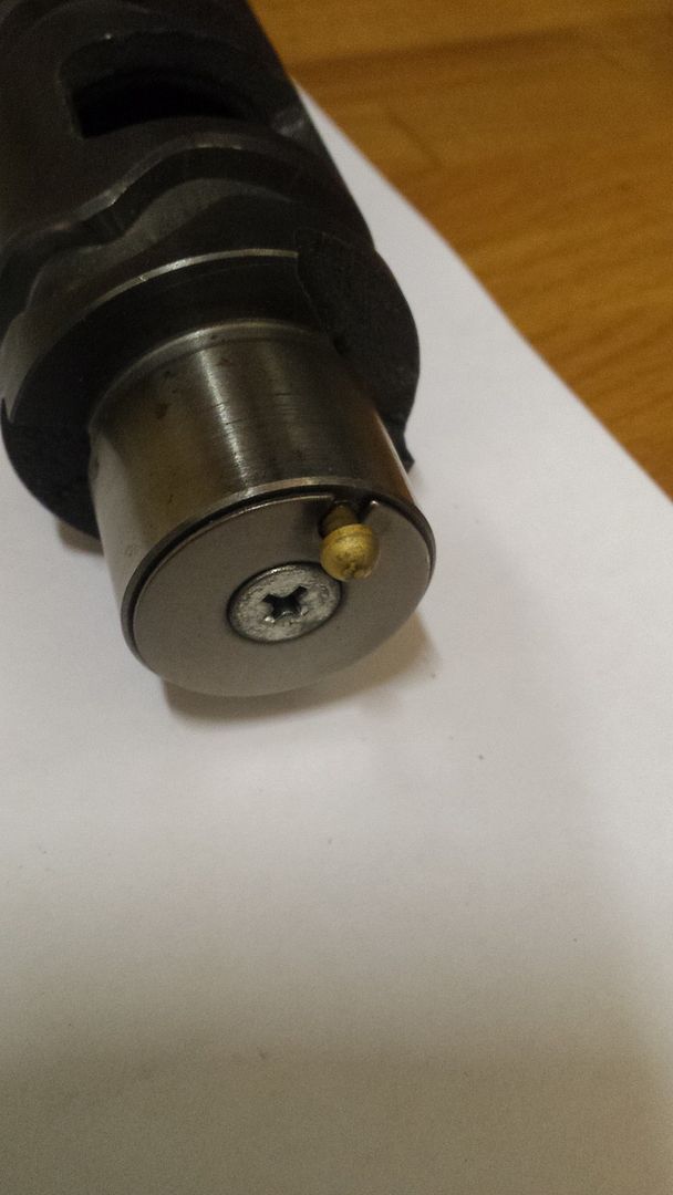 With the new bearing and circlip fitted, the last thing to do is smooth down any rough surfaces on the shift star; 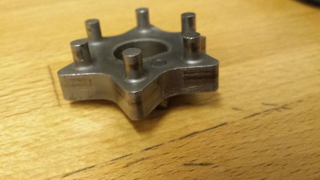 Looks worst than it is, the surface is marked but still fairly smooth to the touch. Still, a bit of emery paper makes it better. There is a pin on the star head that locates in a hole on the drum head, then the cup washer and then a new stainless cap head bolt - M5 12mm shank. I Loctite these in as I don't expect to change it again ! Hi Dusty, Thought I would add this into your thread... When I removed the old selector drum bearing the surface underneath was not as expected! On closer inspection the rough surface looks like the original casting and when it was machined down some of it was left. I don't think it will affect the function of the drum, what do you think? Have you ever come across similar? Sorry, forgot to add photo, doh! Cheers Rich  |
|
|
|
Post by ibby4585 on Apr 19, 2017 15:45:55 GMT 1
Hi Topman I will look forward to seeing your new build start. You do build a lovely bike ! Crank went in today. Before I did, I removed the gear clusters just to check everything was in order - it's some time since I did the gearbox !! Everything was good so on to the crank. Started off by fitting the half ring; 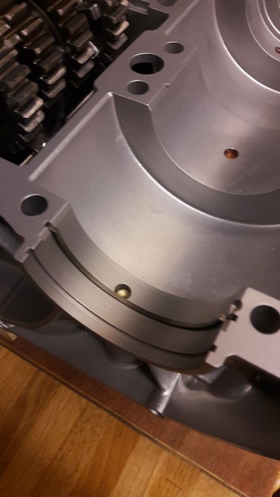 Then lifted the crank in. Note the 4 pins in the bearings sit into the recesses in the bottom case; 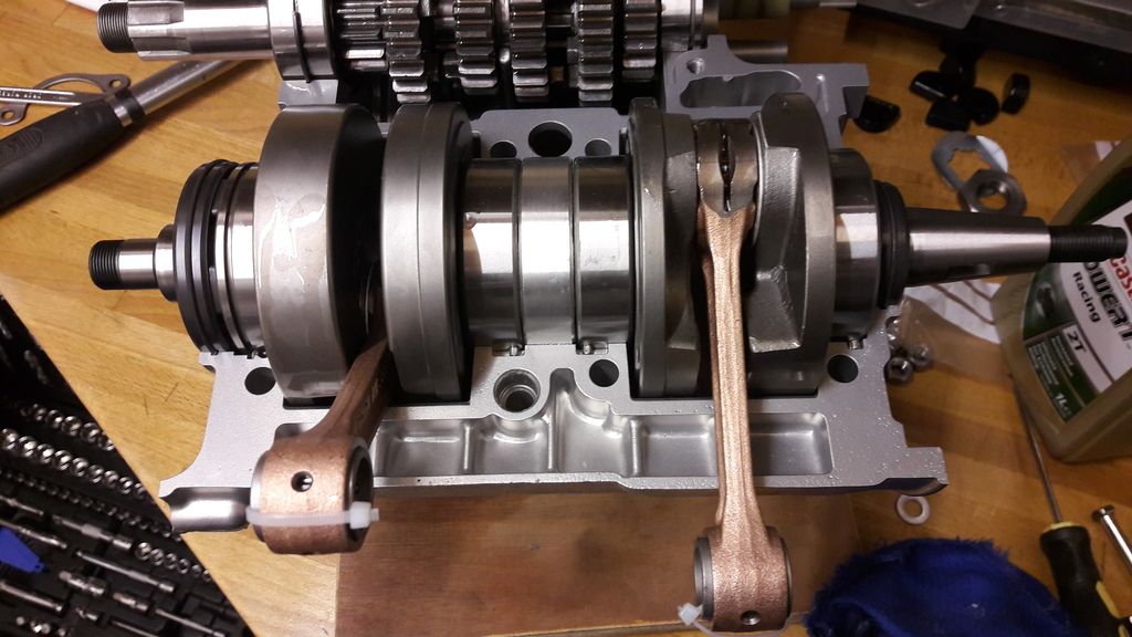 The crank can rock a little at this stage. That's because the centre lab seal needs to bed down in the case as it's a tight fit. A gentle tap with a hammer and wooden drift will seat it. The rotor side crank seal should be fitted before you do this as it's on there to stay now. It's worth packing the seal with grease so it's got some lubricant from the start. At this point I fit the top case and bolt it all together. This helps to seat the crank fully and will also show up any problems. The crank should spin freely as should the gears. Once I am happy, I undo the bolts and nuts and remove the top case, fit the clutch side crank seal - castellations face toward the crank web, give it the grease treatment to the inner seal, then apply the case sealant. I bought a new tube of Threebond 1104 off ebay. It's grey in colour which is handy for silver cases. Once applied I leave it for a few minutes before bolting it all together again. The 8 nuts underneath are the first to get tightened. There are numbers embossed on the case so they are done up in order. I used new stainless nuts and plain washers; 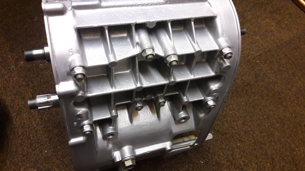 The top bolts are number sequenced too, 9-16. Again I used stainless bolts and washers but I did give them a little polish ! 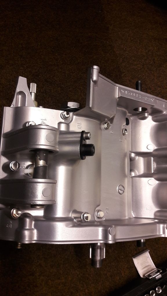 I fit the sprocket seal and clutch pushrod seal before I fully tighten the cases although they can be fitted afterwards if need be. Dusty  Hi Dusty. Could i just ask, at the very top of picture two on this post i can see a gearbox bearing. Its no13 on the yamaha parts list. On my old gearbox it should be a solid cylindrical bearing part number 9331122005. If i can see it correctly yours looks like it has a groove on the outer face for a circlip or half clip? Does it matter? Oddly i just went to order the correct one from pjme as fowlers are out of stock and pjme have incorrectly put the grooved bearing part number instead? Hope this make sense? Kris |
|
|
|
Post by muttsnuts on Apr 19, 2017 16:04:59 GMT 1
The main shaft gearbox bearing is a double bearing and has the groove in it for the retaining ring, this ensurss the bearing cannot float in the casings, if your old one didn't have the groove then it was the wrong bearing fitted in the first place.
I assume your on about the one that is next/behind to the clutch and not the smaller of the two which goes at the other end, if its that one it doesn't matter if it has a groove or not
The double bearing is normally around £40
|
|
|
|
Post by ibby4585 on Apr 19, 2017 16:14:20 GMT 1
Apologies its the smaller r/h bearing in the photo. So that one doesnt matter if it has the groove or not?
Kris
|
|
|
|
Post by Jethro5 on Apr 26, 2017 19:10:29 GMT 1
Still new to the site and just spent a couple of hours going right through this post. Great post although I hope I dont need to reference it anytime soon. Thanks for taking the time .
Regards Brad
|
|