|
|
Post by dusty350 on Mar 5, 2017 22:37:58 GMT 1
I can sleep tonight now it's done  |
|
|
|
Post by Tobyjugs on Mar 5, 2017 22:44:40 GMT 1
Well said Dusty
|
|
|
|
Post by dusty350 on Mar 5, 2017 22:58:54 GMT 1
Yep, you are right. Feel much happier now. It's such a simple job too. The weight of the pistons was just luck. I spose any difference could have been sorted by some careful strokes of the file but the bit of filing I did to tidy up the cuts did the job.
Dusty
|
|
|
|
Post by wallcraft on Mar 6, 2017 8:40:54 GMT 1
There we go , tooth less and all the better for it. Nice job.😃
|
|
|
|
Post by dllc on Mar 6, 2017 18:35:19 GMT 1
hi dusty. brillant thread.
at the risk of drawing the wrath of the professionals on here. do you not use a bit of hylomar or similar on the base and head gaskets?
ta
d
|
|
|
|
Post by dusty350 on Mar 6, 2017 21:42:26 GMT 1
Hi Ordered some new circlips from PJME today so hopefully they will be here tomorrow and I will get the top end back together. Taking up where I left off , the next job was the reed blocks and inlet rubbers. Also the pipe union on the back of the head. I have managed to lose the original union but had a spare from a Ypvs - they are actually the same part number between the Lc and Pv so it bolts straight on. I had striped the reeds off to clean the blocks up and was now ready to refit them. I did clean up the inside edge of the reed blocks to get a good seal for the gaskets; 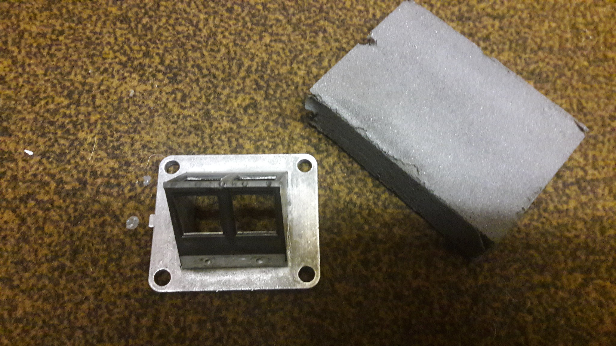 20170304_160633 20170304_160633 by David Miller, on Flickr 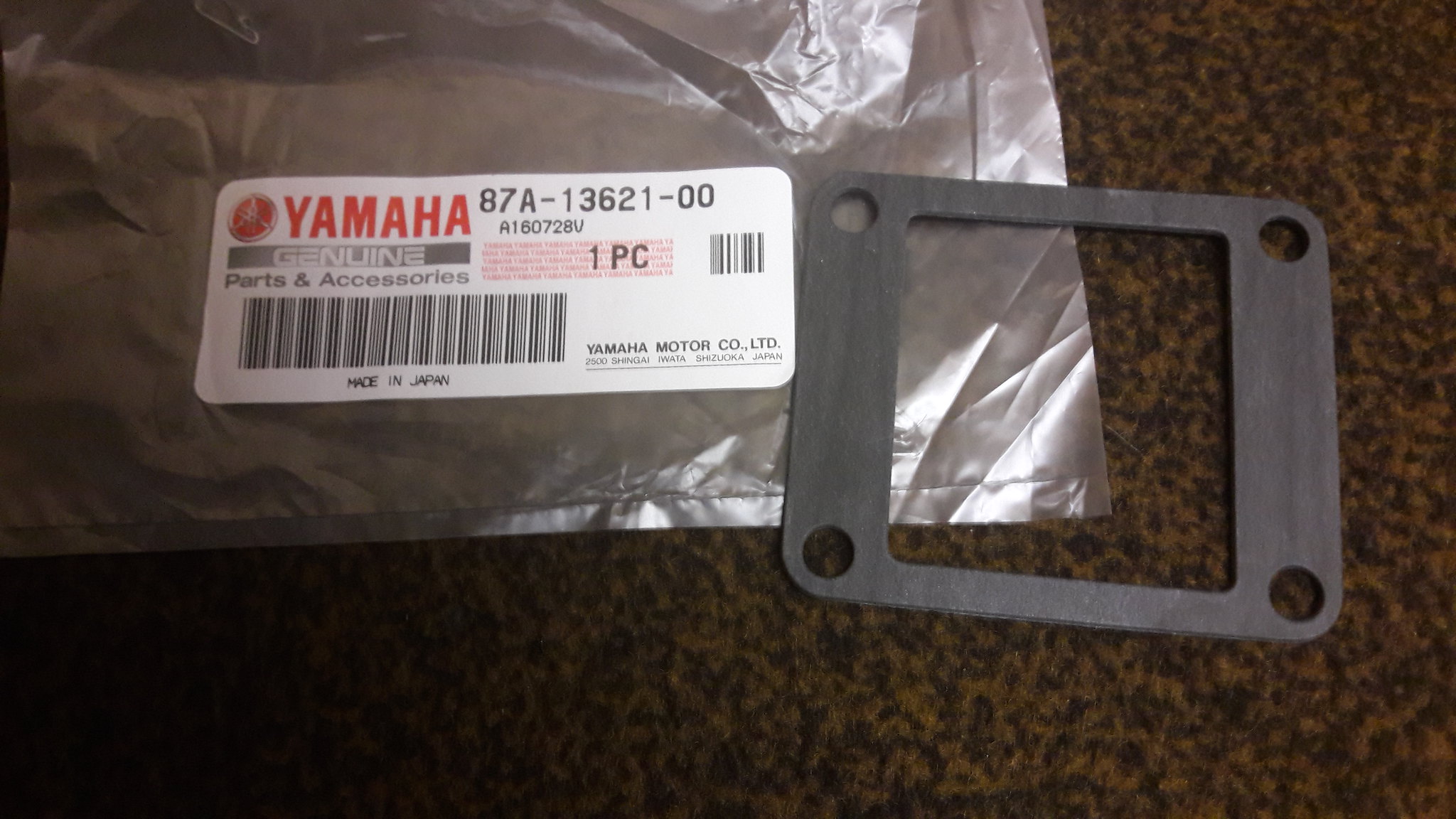 20170304_161554 20170304_161554 by David Miller, on Flickr I also bought new carb rubbers from Norbo. The originals were looking a bit tired and had some crazing in the rubber, and although I'm sure they were serviceable I pushed the boat out and got new ones. The balance tube had a little run over a polishing mop too; 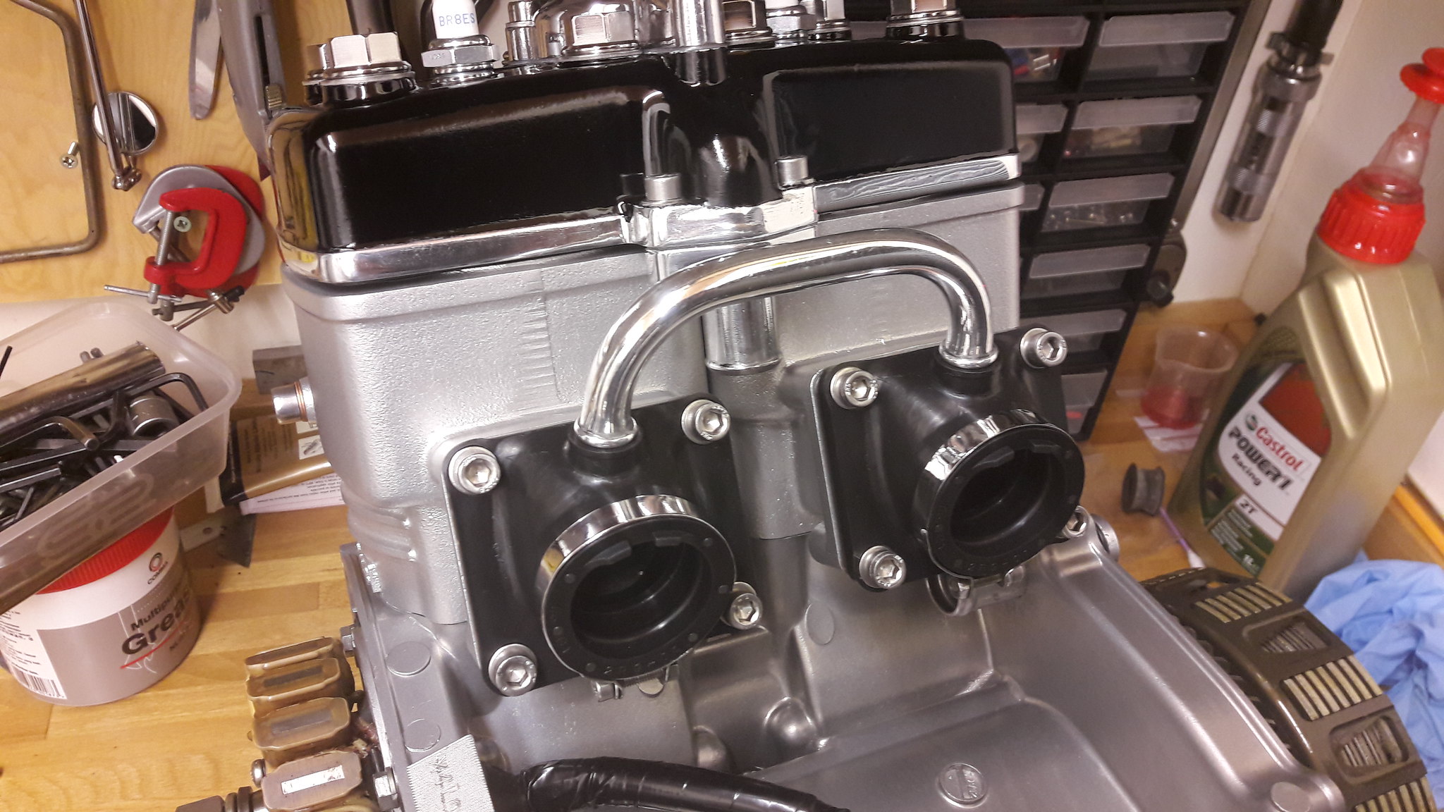 20170304_164826 20170304_164826 by David Miller, on Flickr Another part I'm missing is the hose between head and side case - I've got standard Yam hoses but want a silicon one to match the rest so will need to get an odd one. Plus I'm going to get 2 new balance pipe clips off Norbo - my originals have seen better days ! Dusty  |
|
|
|
Post by ojay on Mar 6, 2017 21:50:26 GMT 1
That looks absolutely stunning dusty 👍👍👍
|
|
|
|
Post by wallcraft on Mar 6, 2017 22:50:25 GMT 1
Very nice Dusty, really like the contrast between the head and barrells.
Mark.
|
|
|
|
Post by 4l04ever on Mar 6, 2017 22:58:28 GMT 1
Another top tip coming...... whenever I have leak down tested my LC engines, the reed blocks and gaskets always leak, so I now put the gaskets and the reed blocks on with some Yamahabond. Saves doing it after the leak down test.
|
|
|
|
Post by 4l04ever on Mar 6, 2017 23:26:01 GMT 1
Mine is Threebond..... :-)
|
|
|
|
Post by mouse on Mar 7, 2017 8:26:09 GMT 1
Engine looks really fantastic Dusty!
Picked mine up at the weekend, will post pics soon
ATB
Mouse
|
|
|
|
Post by dusty350 on Mar 7, 2017 8:44:39 GMT 1
Hi I did use a thin smear of 1104 on the gasket against the barrel inlet face - always do, and in the past have used another gasket between the reed block and rubber, but being new rubbers I didn't do that this time. And I add a thin smear to the underside of the base gasket, just because I always have - probably not necessary with genuine Yam gaskets but hey ho ! I know the vapour blasting is non aggressive but it always shows up small dimples and imperfections in the castings that you don't see before blasting, so I feel a thin layer of goo wont do any harm Hi Mouse, glad you picked your engine up - I bet you are over the moon ! Get those piccys up mate, can't wait to see them  Dusty  |
|
|
|
Post by steven on Mar 7, 2017 9:13:01 GMT 1
Another top tip coming...... whenever I have leak down tested my LC engines, the reed blocks and gaskets always leak, so I now put the gaskets and the reed blocks on with some Yamahabond. Saves doing it after the leak down test. +1 I found the same when doing the pressure/vacuum tests. Hylomar is my prefered gasket goo. steven. |
|
|
|
Post by tgwillis123 on Mar 8, 2017 21:16:14 GMT 1
Another top tip coming...... whenever I have leak down tested my LC engines, the reed blocks and gaskets always leak, so I now put the gaskets and the reed blocks on with some Yamahabond. Saves doing it after the leak down test. I always run an oilstone over surfaces before putting them together, gives you as close to a flat surface as you're going to achieve without a surface grinder! Every little helps and all that haha. |
|
|
|
Post by dusty350 on Mar 8, 2017 21:42:24 GMT 1
Circlips arrived today, so engine is all back together now  I'm hoping my side cases are going to be ready tomorrow. If so I can rebuild the water pump and oil pump shaft and refit. It's getting near to completion now. Dusty  |
|
|
|
Post by 4l04ever on Mar 8, 2017 21:59:19 GMT 1
Are you going to do a leak down test when completed?
|
|
|
|
Post by dusty350 on Mar 9, 2017 8:31:18 GMT 1
Hi I do have the leak down kit that I bought ages ago but have never used it. I will have to investigate how to add the measured amount of air into the engine. I wonder if anyone has any pics they can add ? It would be useful to many building and testing an engine I'm sure. I know the test has been mentioned in a few posts in the past but I've never seen a concise thread on how it's done. I'm not sure how the air is added and measured ? I only have the blanking plugs in the kit I bought through the forum. Any info would be really welcome  Cheers Dusty  |
|
|
|
Post by dusty350 on Mar 9, 2017 20:48:50 GMT 1
Hi Tony There were kits being sold on this forum that enabled you to doing the leak down test to prove or disprove an air leak on an ill running engine. Useful on a finished build to double check everything - belt and braces I suppose but if there was a leak it's easier to sort whilst the engine is on the bench. I always use new Yam gaskets so hopefully no issues, but as I have the blanking plugs and have never used them, it maybe worth adding the process to the thread - except I don't know how you add the air or measure it. Dusty  |
|
|
|
Post by steven on Mar 9, 2017 21:20:29 GMT 1
Hi Dusty, Here is my test stuff I made up. The pressure is added with a bike hand pump via a sharader valve and the vacuum is pulled using my vacuum brake bleeder. I initialy used the four blanking plates on the inlet and exhaust flanges, then I machined the two ally plugs and tested it with the reeds in place also. The pressure is quite low, ie 6 psi and it has to hold it for about 10 minutes or so. I can,t remember how much vacuum, but there are plenty write ups online on how to do it if you have a look. You test both cylinders at once, as the lab seal lets the air pass through it. After that, I pressure tested my cooling system by butchering a radiator cap and utelising a piece of rubber inder the butchered radiator cap to seal the radiator, which means you can test the cooling system to slightly higher than operating pressure without the radiator cap valve opening/lifting. I introduced the pressure to the cooling system via the fitting on the radiator for the expansion hose fitting. You can then re fit your "proper" radiator cap, and check that it is opening at the correct pressure. I found a few radiataor caps that were not opening at the correct pressure. It is a bit of buggering about.....but I felt it was worth it for peace of mind. steven. 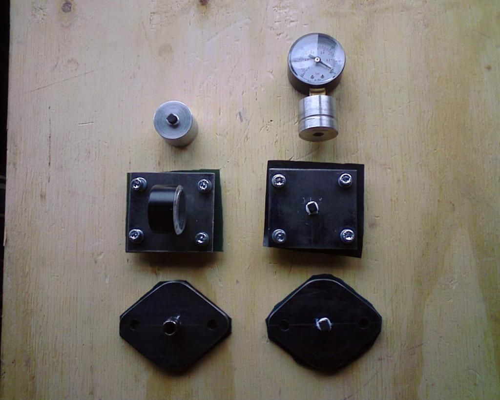 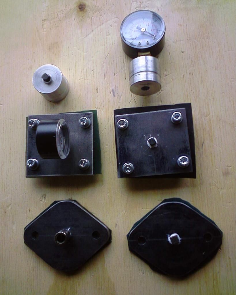 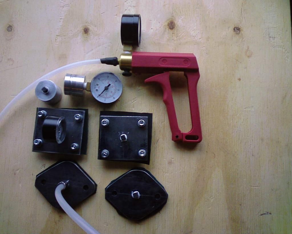 |
|
|
|
Post by dusty350 on Mar 9, 2017 21:29:30 GMT 1
Hi Steven Thanks for posting the pics and how to do it. Bit more involved than I thought. Not sure I will bother as I have plenty going on - I'm fairly confident with the new gaskets so we will see. Thanks again - it will help others I'm sure  Dusty  |
|
|
|
Post by steven on Mar 9, 2017 21:29:44 GMT 1
|
|
|
|
Post by dusty350 on Mar 9, 2017 21:37:30 GMT 1
Picked up my side cases today from Microblast in Windsor. Really pleased with them - powdercoated gloss black. I used the water pump cover and an oil pump blanking plate to cover the essential areas, and they bunged and masked the rest; 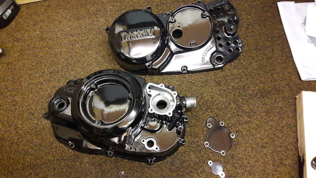 20170309_191336_zpsu1drnlqi 20170309_191336_zpsu1drnlqi by David Miller, on Flickr Got a bit of work to do. I am cleaning the water pump volute - it had some limescale in it so I'm taking this opportunity to give it all a good clean out and light polish. The left hand case will need a bit of work to fit the bearing I bought to replace the missing gear shaft spacer, so a bit of gentle dremelling should enable me to press it into place. I plan to fit the water pump and oil pump sprockets and refit the casing. I will add the oil pump after I've got Arrow to work his magic on it ! Dusty  |
|
|
|
Post by dusty350 on Mar 9, 2017 21:38:49 GMT 1
Thanks for the link Steven  Dusty  |
|
|
|
Post by steven on Mar 9, 2017 21:46:55 GMT 1
Hi Dusty, No probs. I also was confident, as I used all new gaskets and a calibrated Britool tourqe wrench to meticousely build my engine, or so I thought. ....and I found several leaks which I had to rectify ! :-( I just felt that I had spent so much time and money rebuilding it all, that I wanted the peace of mind, and I didnt want to be in a situation farther down the line wondering if it had air leaks, so I decided to do all the tests, which were a bit of fannying about, ......but Elsie is worth it ! :-) I understand about having lots going on only too well m8 ! They said computers were going to save us all time..... where is all this fekin time that they said computers would save us  Cheers. steven. |
|
|
|
Post by steven on Mar 9, 2017 22:08:24 GMT 1
|
|
|
|
Post by dusty350 on Mar 9, 2017 22:26:43 GMT 1
That's a great tool  Do you need to have the bigger plate or could you use a slightly bigger rectangular plate to bridge the front of the impellor housing ? Dusty  |
|
|
|
Post by steven on Mar 9, 2017 22:30:47 GMT 1
..... im sure a rectangular type plate would work too Dusty.
steven.
|
|
|
|
Post by dusty350 on Mar 9, 2017 22:35:16 GMT 1
Great, that may be a job for tomorrow if I get a chance. Good of you to post it - I'm sure we can all make something like that easily enough, and save damaging a bearing when fitting it  Dusty  |
|
|
|
Post by dusty350 on Mar 11, 2017 22:41:21 GMT 1
Hi The engine is really coming on now. I thought I would fit the water pump next now the cases are back. I spent some time cleaning up the inside of the clutch case and all the water passageways before fitting the seal and bearing. I liked Steven's idea of a tool for drawing the bearing into position, but my problem at the mo is I am ripping down my old shed/workshop so all my tools are packed away and ability to make stuff is compromised. So I just used some washers and a long bolt and nut to do the job. So, long bolt passes through the washers and then through the front of the pump volute; 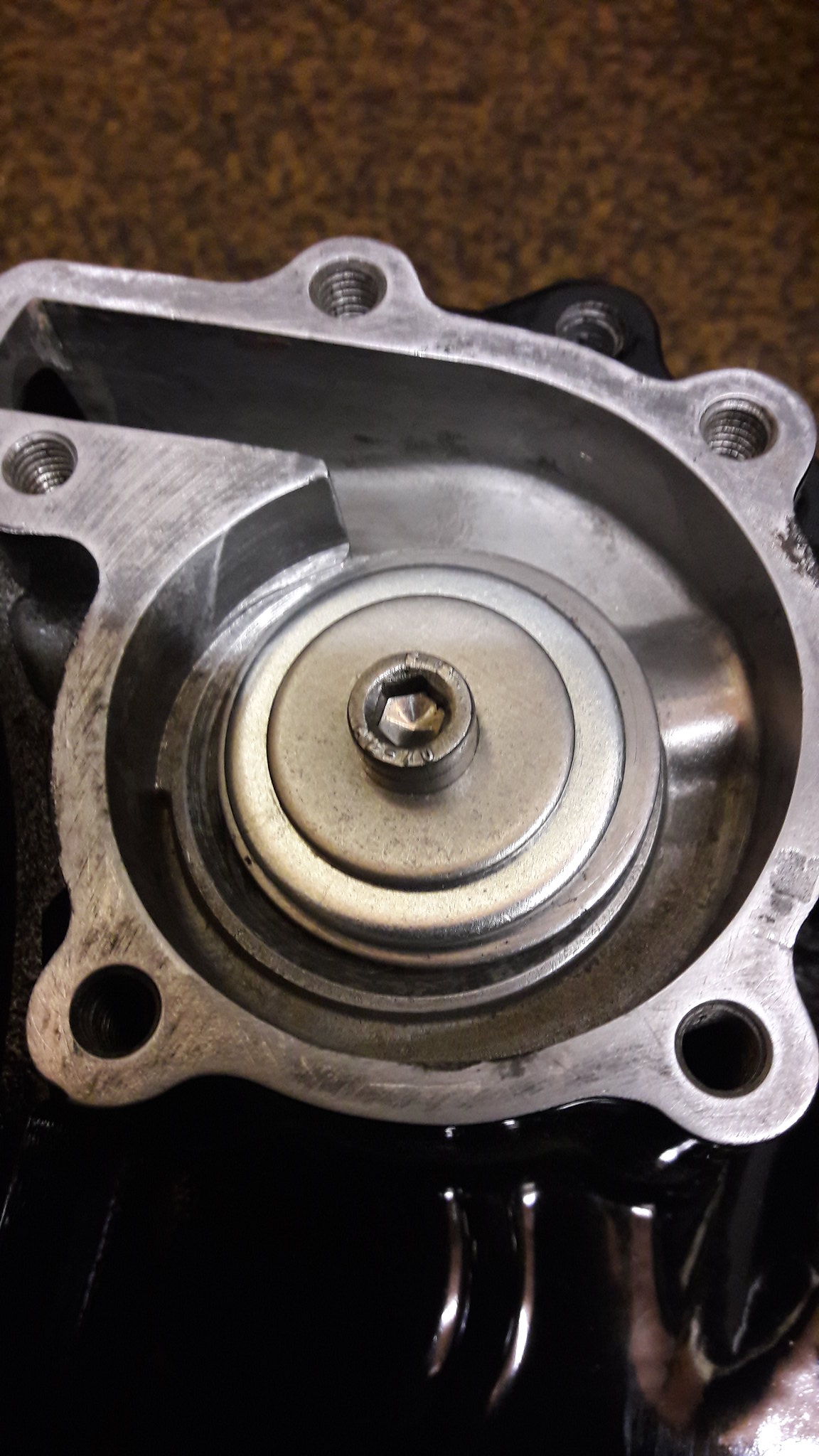 20170309_223457 20170309_223457 by David Miller, on Flickr The bolt passes through the loose seal which is sat in the housing it fits into. Then another washer the same size as the seal, and then the nut. Tighten the nut and the seal - whose edge was lightly greased, is pulled into place. The seal actually says "Water side" on it so you don't get it the wrong way round !!; 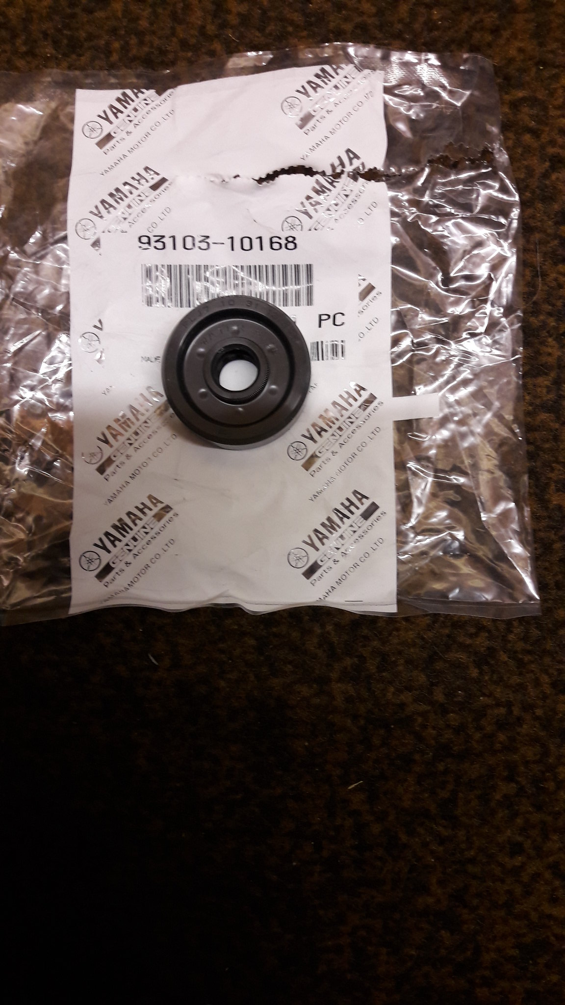 20170309_220933 20170309_220933 by David Miller, on Flickr Once I was happy the seal was seated correctly I did the same process with the bearing. Really easy doing it this way and no damage to seal or bearing by having to knock them in. I bought a new impellor from Norbo; 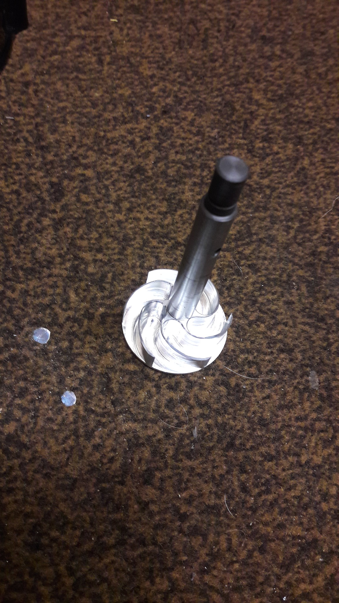 20170309_224908 20170309_224908 by David Miller, on Flickr Lightly greased the shaft and the inner part of the seal and slid it through, fitting the pin and then the sprocket; 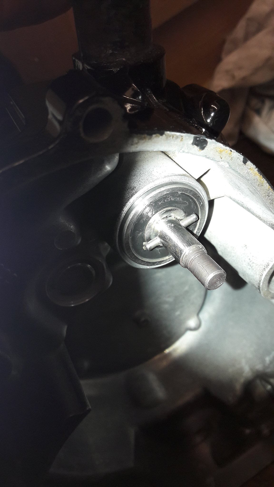 20170309_225339 20170309_225339 by David Miller, on Flickr 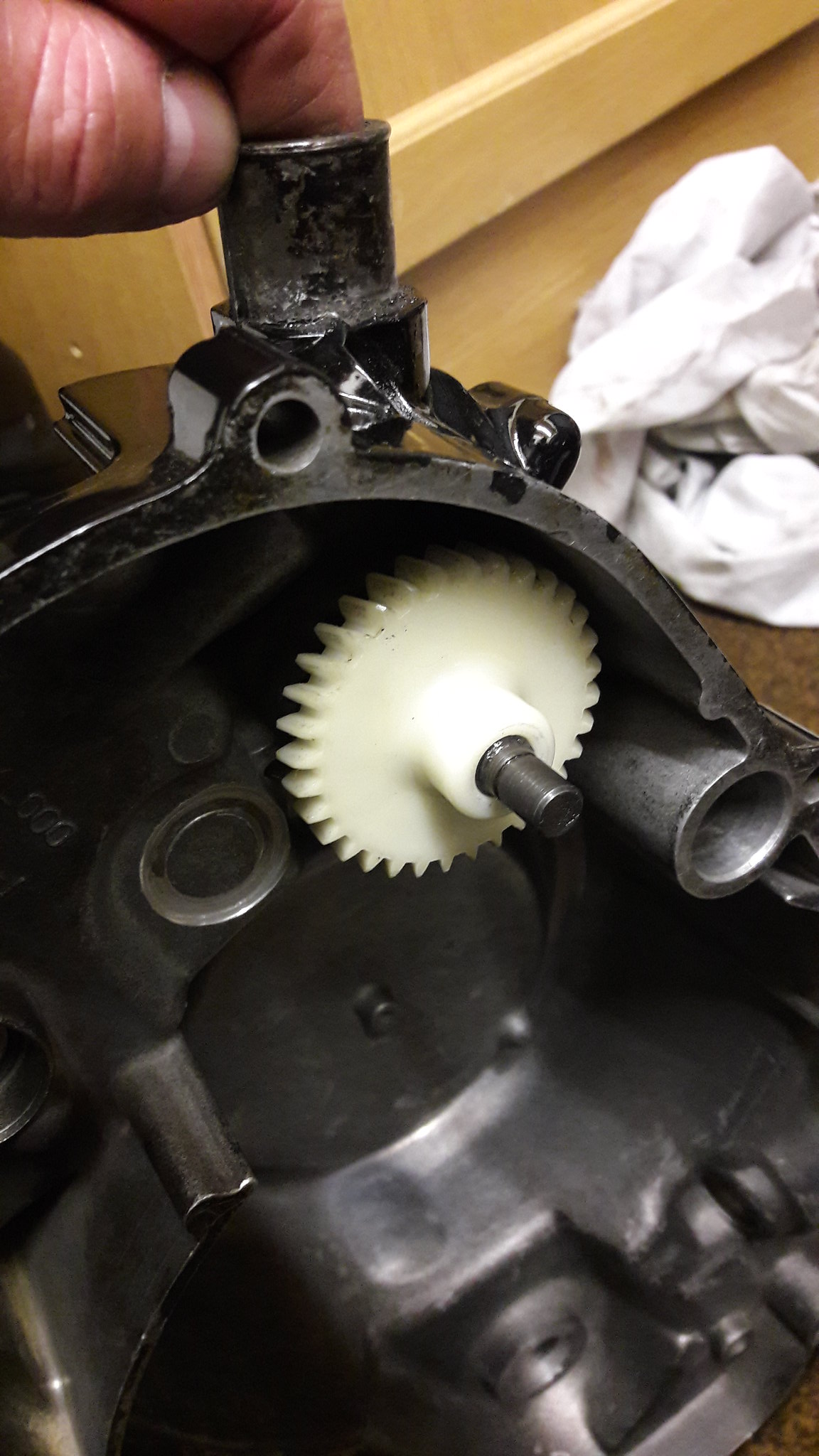 20170309_225359 20170309_225359 by David Miller, on Flickr 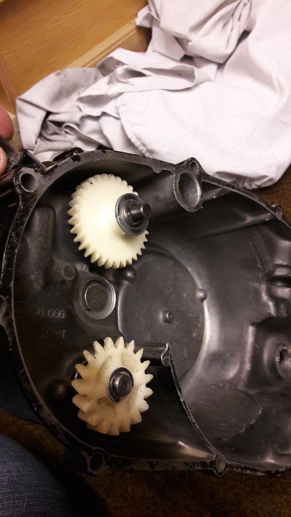 20170311_100316_zpsrohpojvm 20170311_100316_zpsrohpojvm by David Miller, on Flickr You can see in that last pic I have fitted the oil pump shaft and seal and sprocket. The seal pushed into it's housing so no need to use the draw bolt method. The case can now be fitted. I have done this temporarily as I want to time the engine with a dial gauge before I bolt the casing on for the final time Reason being, the next part to fit is the rotor, and I needed to lock the crankshaft again to do the rotor bolt up tight. First thing was to fit a new woodruff key; 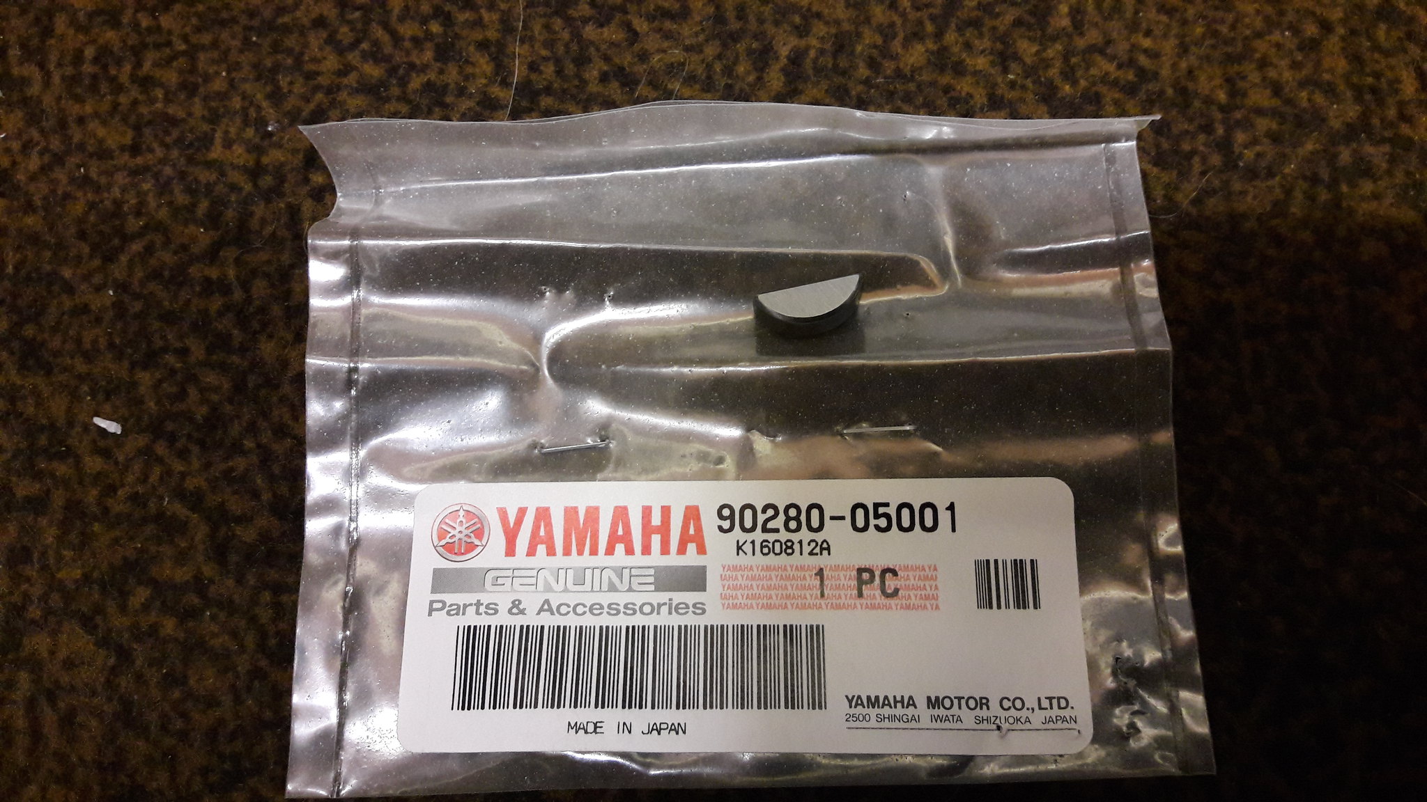 20170311_091553 20170311_091553 by David Miller, on Flickr This was actually really fiddly. The new key has an indent from a punch on one side - I presume to make it a tight fit in the cranks groove. It was impossible to fit it with the generator in position so I had to undo the genny and move it out of the way. I could then, very gently, tap the key into the groove. Genny back on; 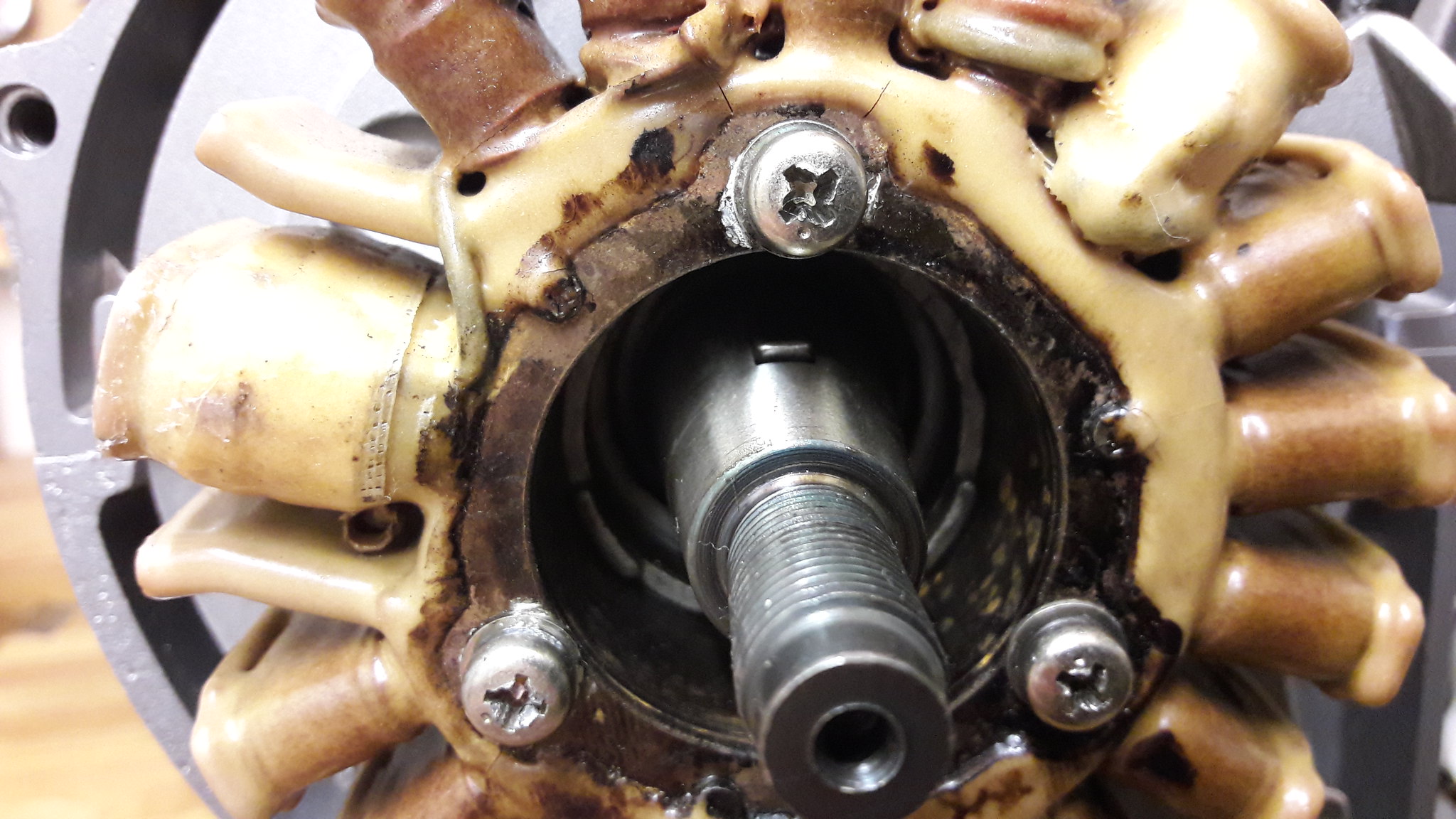 20170311_094803 20170311_094803 by David Miller, on Flickr And then the rotor; 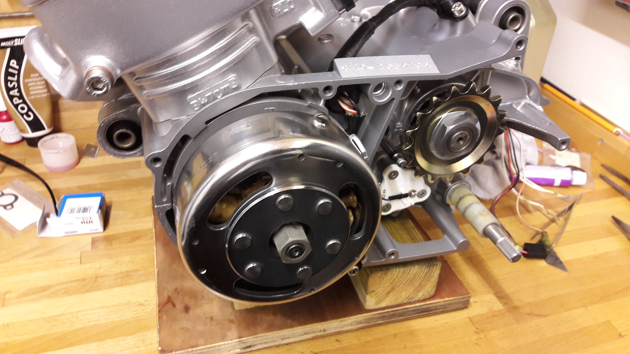 20170311_095918 20170311_095918 by David Miller, on Flickr I did the nut up by locking the clutch and primary gears with my bit of flattened copper pipe which works a treat. Dusty  |
|
|
|
Post by dusty350 on Mar 11, 2017 23:01:20 GMT 1
The left side casing was missing the spacer in the gear shaft hole. After measuring I bought a needle roller bearing from Simply bearings to solve the problem. I wanted it to be a tight fit, and had to use my dremmel with a circular sanding attachment to remove some alloy from inside the hole. Doing it a little at a time so as to not make the hole too big - I managed to get the bearing in - a nice tight fit and aligned for the shaft to give support;  20170311_123957 20170311_123957 by David Miller, on Flickr Dusty  |
|