|
|
Post by jon on Jan 28, 2017 19:42:04 GMT 1
I have made a few Lexan windows for the clutch cover in the past, but wanted to try making a detachable cover out of billet aluminium as an alternative. Having a removable cover is a bonus as you can either change clutch springs easily without a coolant drop, or just have a quick nosey at the engine oil. Anyway I machined up these covers from aluminium Clear 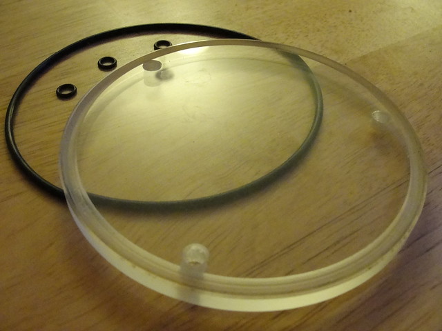 Aluminium  To be fair they were a pain in the arse compared to the Lexan windows, and that's why I ended up with 3 and not 4 as I messed one up. I will probably end up polishing one for this project as it will be bling, and anodising the other 2 black. Jon |
|
|
|
Post by JonW on Feb 7, 2017 23:48:42 GMT 1
Youre on fire Jon! Tho I will admit that if youre like me that once you get into fabbing stuff for your bike it tends to roll on and you end up with more ideas than time  |
|
|
|
Post by lrcarl on Feb 8, 2017 10:41:18 GMT 1
Nice work Jon
Been trying to get local guy to make me one
But doesn't seem interested
If you make anymore can you put me down for one
Thanks carl
|
|
|
|
Post by jon on Feb 15, 2017 19:53:16 GMT 1
I welded my extra swingarm gussets on at the weekend. But due to the fact they were 5mm thick, the weld was industrial looking. I left it until today to decide what to do. I cleaned the welds up, and proceeded to run a 'cosmetic' weld over the top. This didn't work well due to the length. I decided in the end to just smooth it all off. 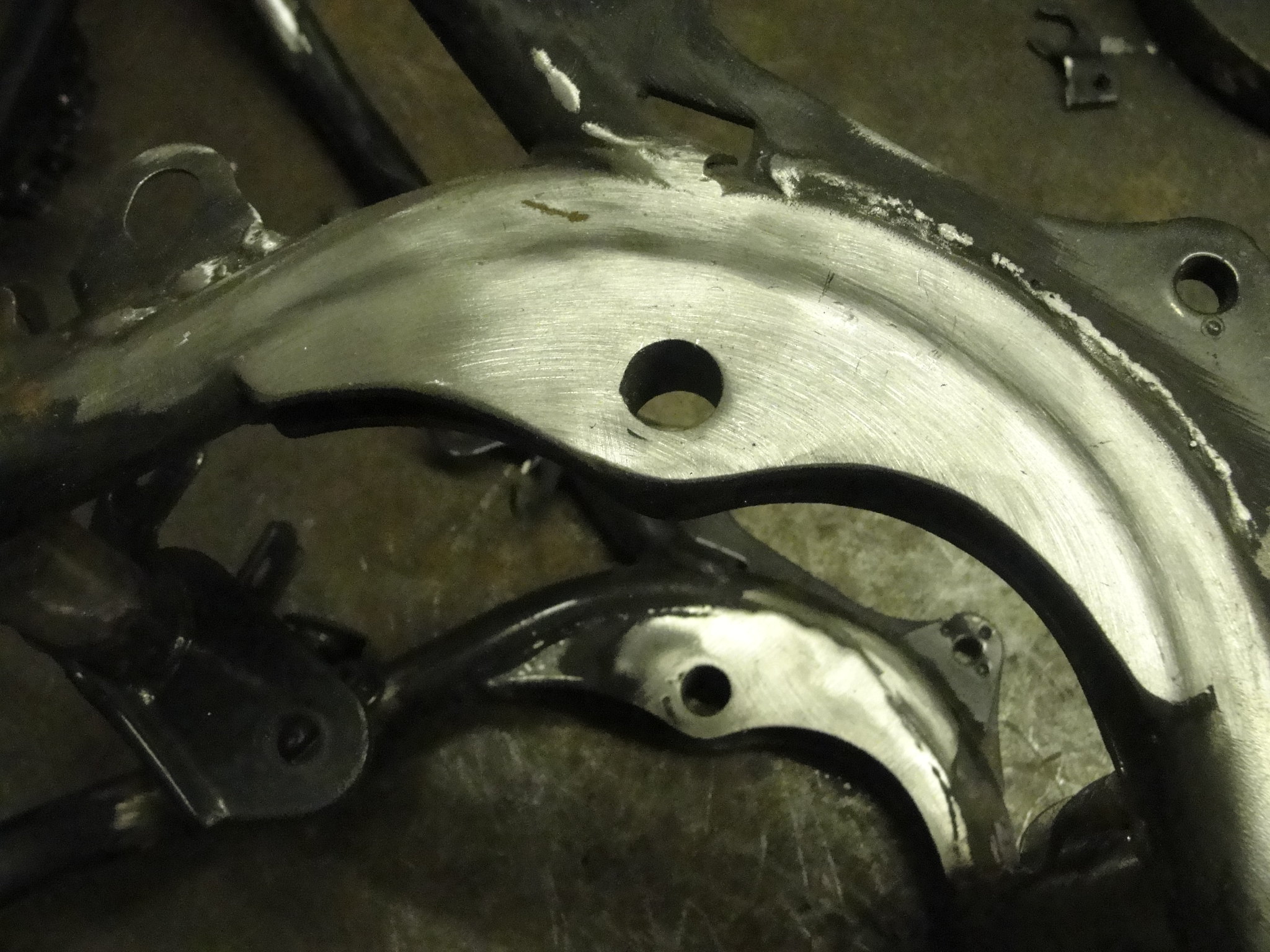 Jon |
|
|
|
Post by spudmab on Feb 15, 2017 20:16:55 GMT 1
Looking good,
What welder do you use.
|
|
|
|
Post by jon on Feb 15, 2017 20:42:58 GMT 1
I have a Portamig 215.
Bought as it was UK made (if not all the parts are, drive is Swedish I think?).
I bought the 215 as it had better electronic control (no relay) over the 185. This is down to my style of welding.
While MIG is easy to master, I've practiced now DIY for 30 years.
Jon
|
|
|
|
Post by spudmab on Feb 15, 2017 21:18:56 GMT 1
Looking good, very impressed by the amount of projects and work your doing.
|
|
shelby
L plate rider.
 
Posts: 33 
|
Post by shelby on Feb 16, 2017 0:52:55 GMT 1
Fair play thats some job
|
|
|
|
Post by dusty350 on Feb 16, 2017 8:35:57 GMT 1
Great skills as usual Jon  Are you planning on closing in the front part of the bracing ? Dusty  |
|
|
|
Post by jon on Feb 16, 2017 20:18:24 GMT 1
Dusty, I don't think closing the front will add any mechanical difference, and to be honest I think it would look too boxy.
The YPVS is closed, but of course it is rounded.
Jon
|
|
|
|
Post by dusty350 on Feb 16, 2017 21:48:41 GMT 1
Hi Jon I saw Mark Dent's Facebook page a day or 2 ago and he has done the same but closed in the front. I don't know if you've seen it - I will try and find a pic if you are interested. Dusty  |
|
|
|
Post by dusty350 on Feb 16, 2017 21:56:03 GMT 1
|
|
|
|
Post by dusty350 on Feb 16, 2017 21:59:14 GMT 1
Interesting pic of the Lc frame to the side of the main pic, showing where they have added extra supports. Looks like it's from a Jap site. Dusty  |
|
|
|
Post by jon on Feb 17, 2017 0:04:41 GMT 1
Dusty, I have to admit it looks better than I thought it would.
I still think it's cosmetic when you consider the forces involved.
Jon
|
|
|
|
Post by JonW on Feb 17, 2017 8:42:08 GMT 1
I agree, it'll stop the crud getting in, but really its just neatening it up really. Interesting the pic of the Japanese frame strengthening design, which i assume is not using the LC shock mounts as there is a plate thru it!  |
|
|
|
Post by dusty350 on Feb 17, 2017 9:34:38 GMT 1
Hi I did wonder if that frame was destined to have a Ypvs style suspension set up. I had an Lc - modified by Hejira - that used a pv swingarm and suspension and the top mount was along the same lines; 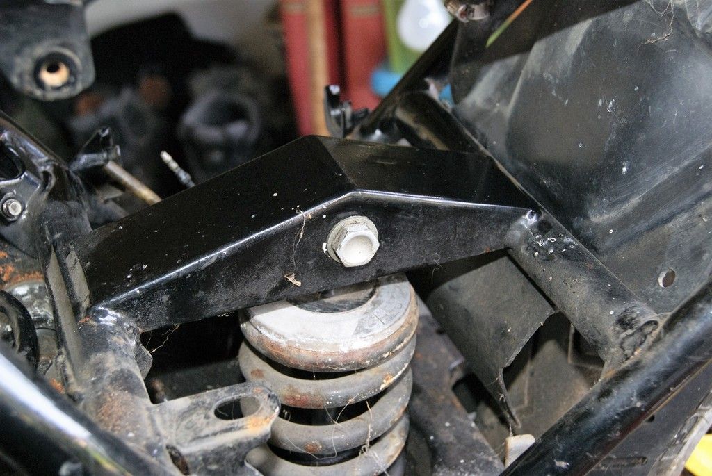 They double upped on the cross brace at the bottom so the bottom link had a stronger fixing point; 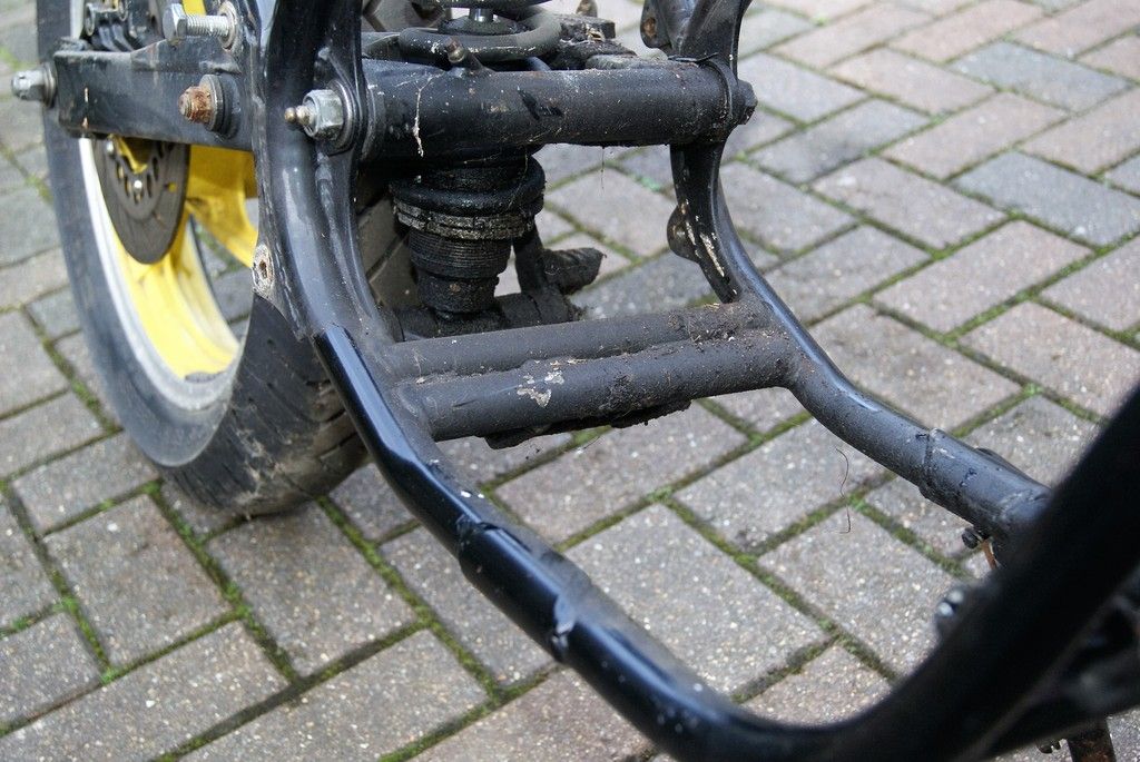 Downside was you couldn't use an airbox as the top mount was in the way. It was nicely done though. Dusty  |
|
|
|
Post by ukcalling on Feb 19, 2017 14:04:09 GMT 1
Jon seen your work fitting tie bar brackets to a 1980 frame.
I am after a little help if possible - do you have a pattern for the brackets you made up as need to do the same?
Appreciate your help
Thanks Nick
|
|
|
|
Post by jon on Feb 26, 2017 20:51:59 GMT 1
I managed to weld the LC frame up this weekend. I welded the strengtheners in I had made from bending 20mm tube, and also welded the half finished OEM welds. 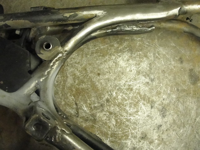 Jon |
|
|
|
Post by JonW on Feb 27, 2017 1:04:10 GMT 1
The curved pipes follow the line of the curved spars which is aesthetically pleasing so well worth the effort.  and yes I know just how much effort it is to slowly cut the tubes back to get them notched to fit the existing spars properly, slowly slowly catchy monkey I think people used to say LOL Welding these frames can be tough, they have so much leached in oils and other crap its not easy to get a nice weld we found when doing mine, especially with TIG. MIG is better but you do get spatter, tho if you look at the frames you can see Yamaha got that when they did it in the factory too! That said, I do agree with Tony that wire speed is a funny thing on a MIG, ive only recently learnt that slowing the speed is often the key to a better weld, the opposite of what felt right to me intuitively. Either way, welding tips aside, Im liking the direction youre going Jon |
|
|
|
Post by jon on Feb 27, 2017 8:43:37 GMT 1
As you said Jon, cutting the gussets to fit the spars is time consuming. They were close enough, but still had very slight gaps. This caused a couple of blow throughs, so I ended up just stitch welding it as I wanted it fully penetrated. That and the fact you can't get the welding touch close enough because of the upper radiator bracket, meant the welds are not the prettiest, but are very functional. However as said they perfectly match some of the OEM welds  . Jon |
|
|
|
Post by JonW on Feb 27, 2017 9:25:46 GMT 1
yeah that rad fixing is a bitch to get round, I ended up cutting back my gussets so i could weld to the frame there, then after went over the lot again to tie it into the rad mount as well.
ahem, the OEM welds are shocking at times, even the jig wasnt very good if you look around, Ive got spars that are a bit over the place and then were welded in anyway on my frames, the ones I did were not done like that LOL
|
|
|
|
Post by jon on Feb 27, 2017 10:40:22 GMT 1
Jon, I know what you mean about alignment.
The cross member joining the two spars from the bottom of headstock looks like it was not even lined up by eye. Every frame I see is at a different angle.
I'll probably neaten up the gussets next time i get the welder out.
Jon
|
|
|
|
Post by jon on Feb 27, 2017 20:07:37 GMT 1
More welding done on strengthening the frame in places no-one will ever see; apart from me.  Jon |
|
|
|
Post by jon on Feb 27, 2017 23:16:28 GMT 1
When I welded the extra swingarm brackets in they were slightly more of a gap from the frame tubes than I would have liked. That's why I had to weld side to side, and it looked a bit industrial IMO. When I realised this, I built up the weld, before grinding back the surface.
Another very important thing I learnt in my apprenticeship/college was the 'stress raiser'. In most cases a smooth fillet radius actually spreads any forces out, whereas an abrupt change (such as a weld) can increase the force in that particular area, leading to failure (IF it isn't over engineered - safety factor).
Jon
|
|
|
|
Post by JonW on Feb 28, 2017 0:16:12 GMT 1
Interesting discussion. Im always keen to learn more about welding and know exactly what Tony means when he says that MIG is easy to do, but hard to do well. I've 20 or so years on/off experience with welding MIG and never been taught and always wish that someone would teach me, but Ive found that running a weld is like playing racquet sports, you absolutely know when you get it right. Anyway, always good to hear welding advice.
I'd forgotten about the tie bar mounts, I also welded mine on the B side Jon, Yam only welded on one side... same with the top rear shock mount, which ive tied to my new upper spars and their cross piece.
|
|
|
|
Post by jon on Feb 28, 2017 0:23:39 GMT 1
Both JonW and me are strengthening frame for slightly different reasons.
Mine is purely for handing, whereas JonW's is also to handle extra power.
However we both have the same goal of stiffer front and rear, coupled with modern suspension. Effectively this means the frame will flex more, because the forks and swingarm won't!
That's why we are strengthening.
I have a few RDs to ride and compare once this is done to see how much (/if...hopefully-probably) it is improved.
Jon
|
|
|
|
Post by yamark on Feb 28, 2017 21:56:09 GMT 1
Jon, those curved tubes look really good - very impressed. It is hard to make frame mods, as the factory welds are "basic" to say the least. As soon as you use a flap wheel to tidy up welds, it starts to look very different from the factory finish. I think you've done really well. I had a couple of goes at my front frame tubes before they "looked right"
Enjoying your progress mate  |
|
|
|
Post by jon on Mar 7, 2017 1:00:47 GMT 1
Not much progress, I'm afraid, but some. I welded in some braces either side of the centre stand cross member. Originally there was only one, which I thought a bit odd? 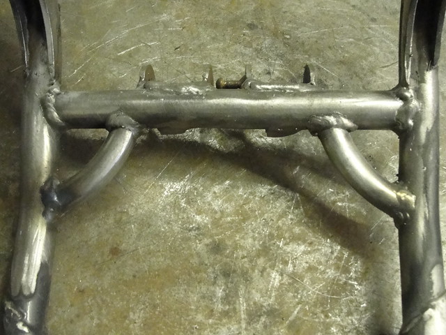 Now I realise for optimum strength they should have been straight or maybe even curving inwards, but I'm sure they are better than original (in terms of strength). They were done like this for two reasons. Firstly to enable me to get the welding torch up close, and secondly because I think they look good like this. Jon |
|
|
|
Post by JonW on Mar 7, 2017 2:18:43 GMT 1
I think it only has one as its on the chain side, where the power is and where the engine twists etc.
I like the look of the curved braces, I used the two straight half tubes from the ypvs frame on this part and yours are longer and full tube, so I would think stronger.
|
|
|
|
Post by jon on Apr 11, 2017 21:02:55 GMT 1
Well, I wondered whether to post this on a different thread; but seeing as I'd posted the first of the billet clutch covers on this one I thought I would post on here. Some time ago a few showed interest in anodising, so I thought I'd show a bullet point guide of the process. First rule is safety, as there are two dangerous substances used here. Eye protection, gloves, mask and water on hand is a must. 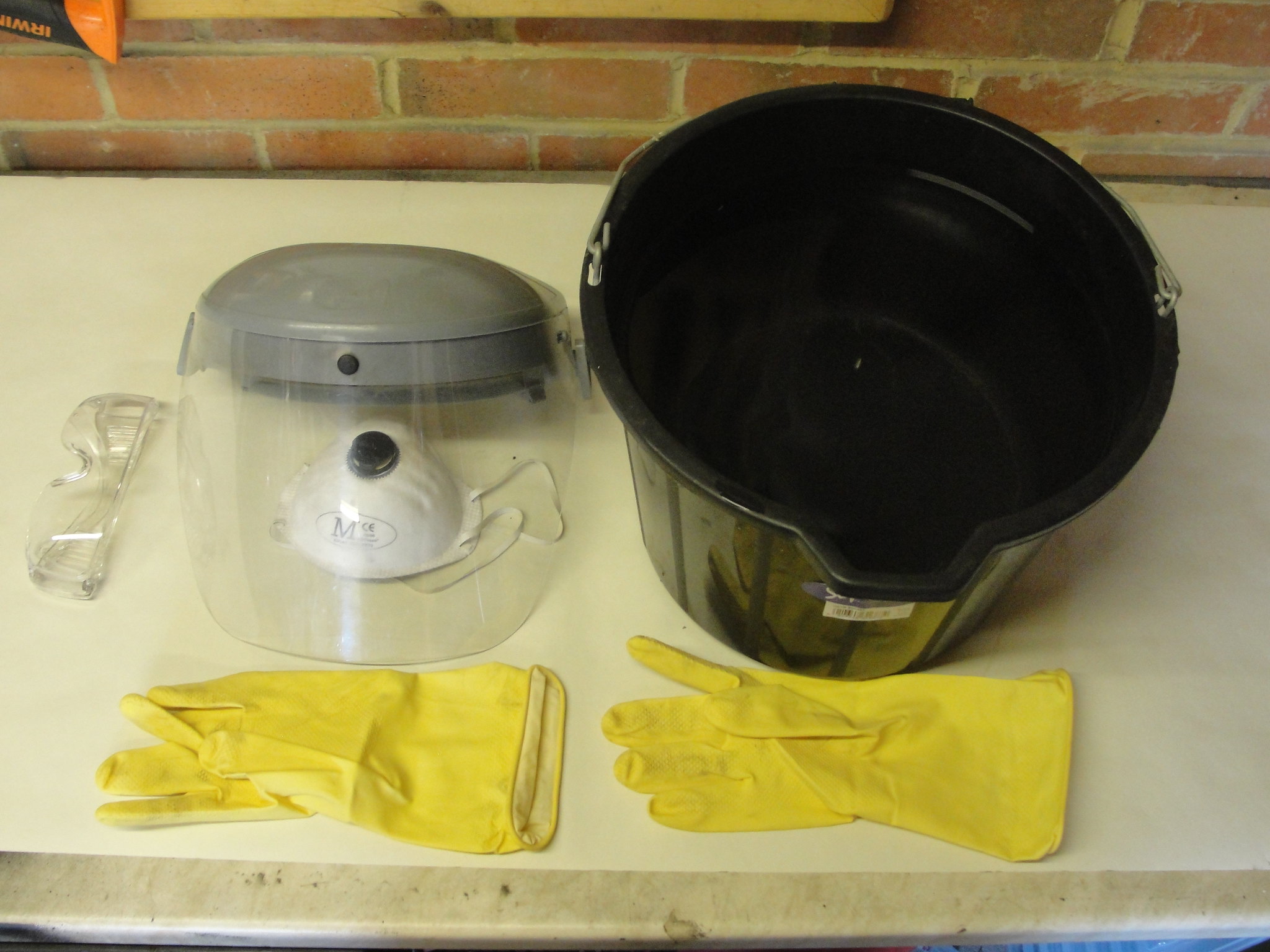 The electrolyte (solution the part is dunked in) is a 15% solution of sulfuric acid in de-ionised water. The water is important as tap water has all sorts of minerals and additives which effect the finish. Battery acid is 30% sulphuric, so cutting it 50/50 is easy. 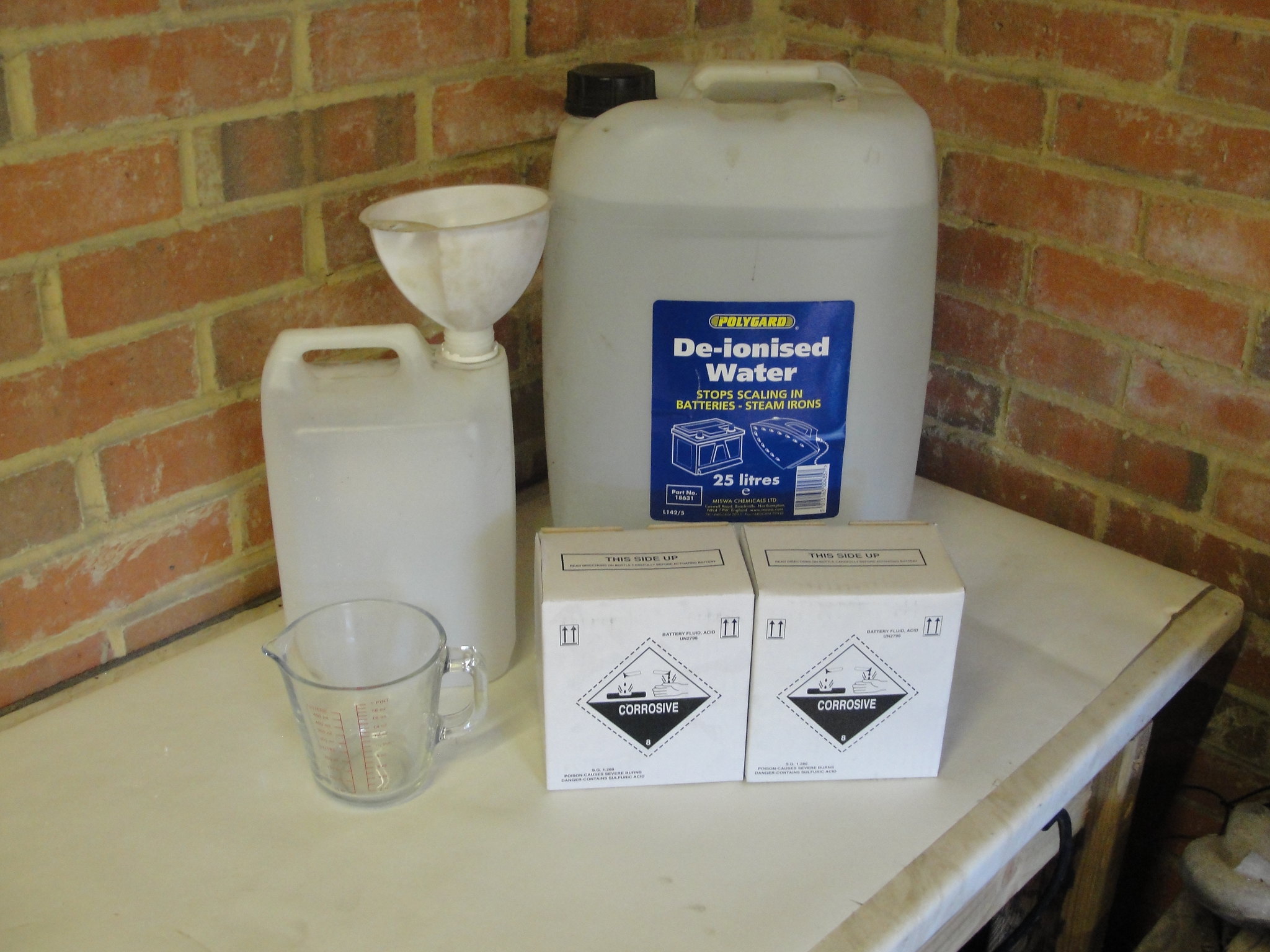 Next up is cleaning the piece from all traces of grease. Maybe over the top, but first I spray it with carb cleaner. Just look at the crap on the tissue. 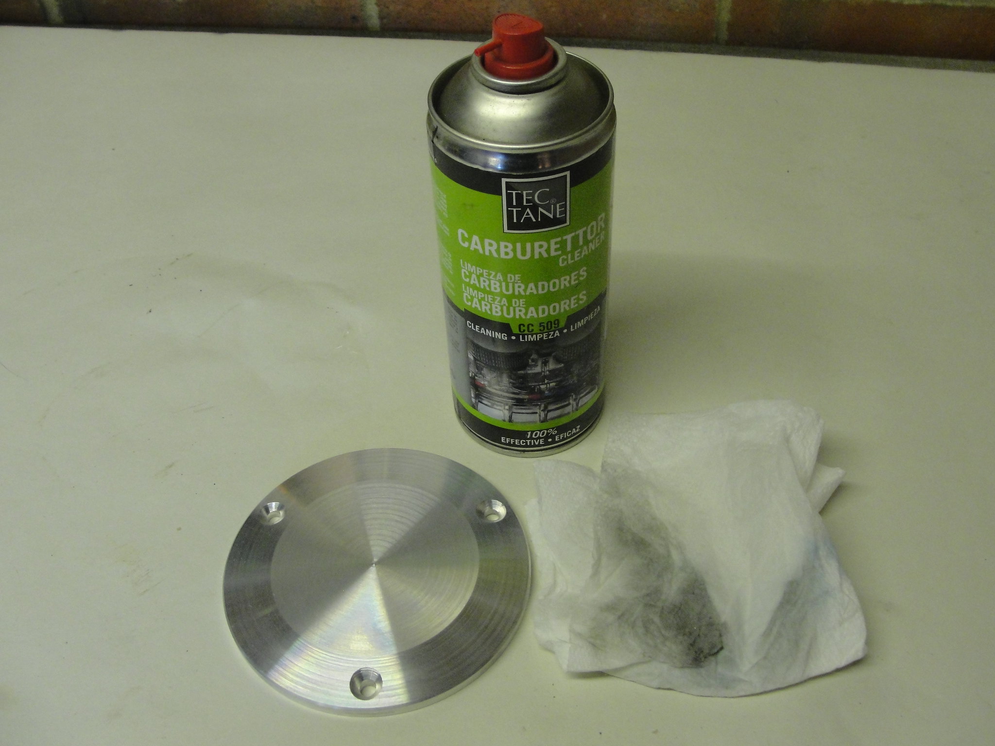 Next is scrub it with gloves on in soapy water. The after a rinse, it's into the lye. Now this just caustic soda diluted in water, and will melt a layer off the aluminium. This is one case where you should do the exact opposite of the instructions. You actually want the stuff that will melt aluminium. Just don't leave in for too long! 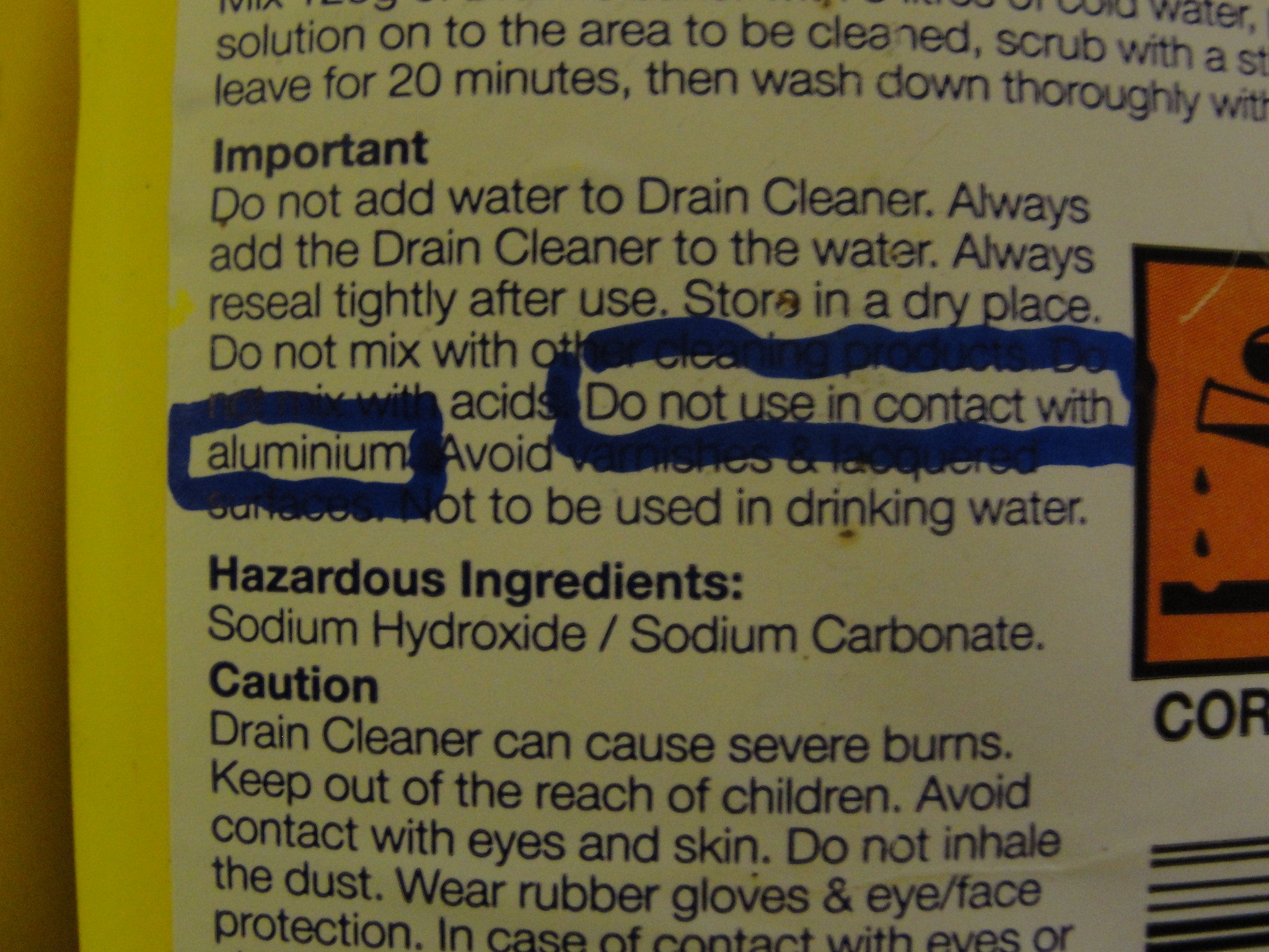 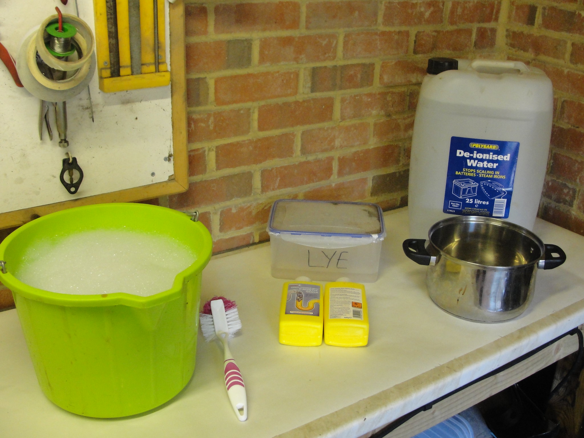 Next is the tank itself. You must use lead as the cathodes, and hang the piece off the positive charge. 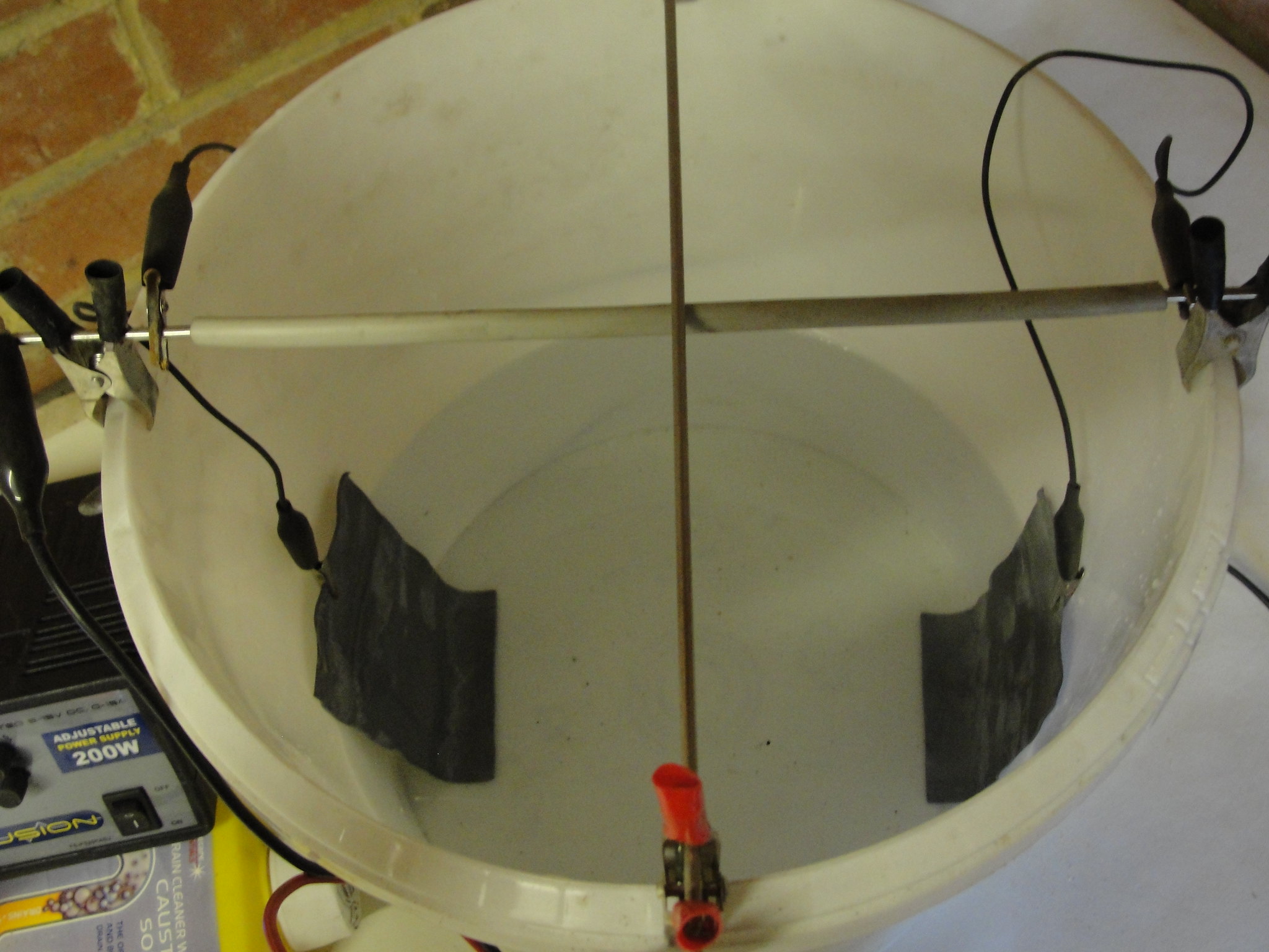 The power supply is adjustable for voltage and ampage. On a new tank I use around 15V, and once worn in you can drop to 12V. Amapage is worked out by measuring the surface area of the piece in cm2. As a general rule you should aim for an hour of anodising based on 0.013 amps per cm2.  Once anodised you can dye it if you like. The surface is pourous, and so will absorb dye. Here I am doing it black. The dye is heated and adjitated to give an even finish. 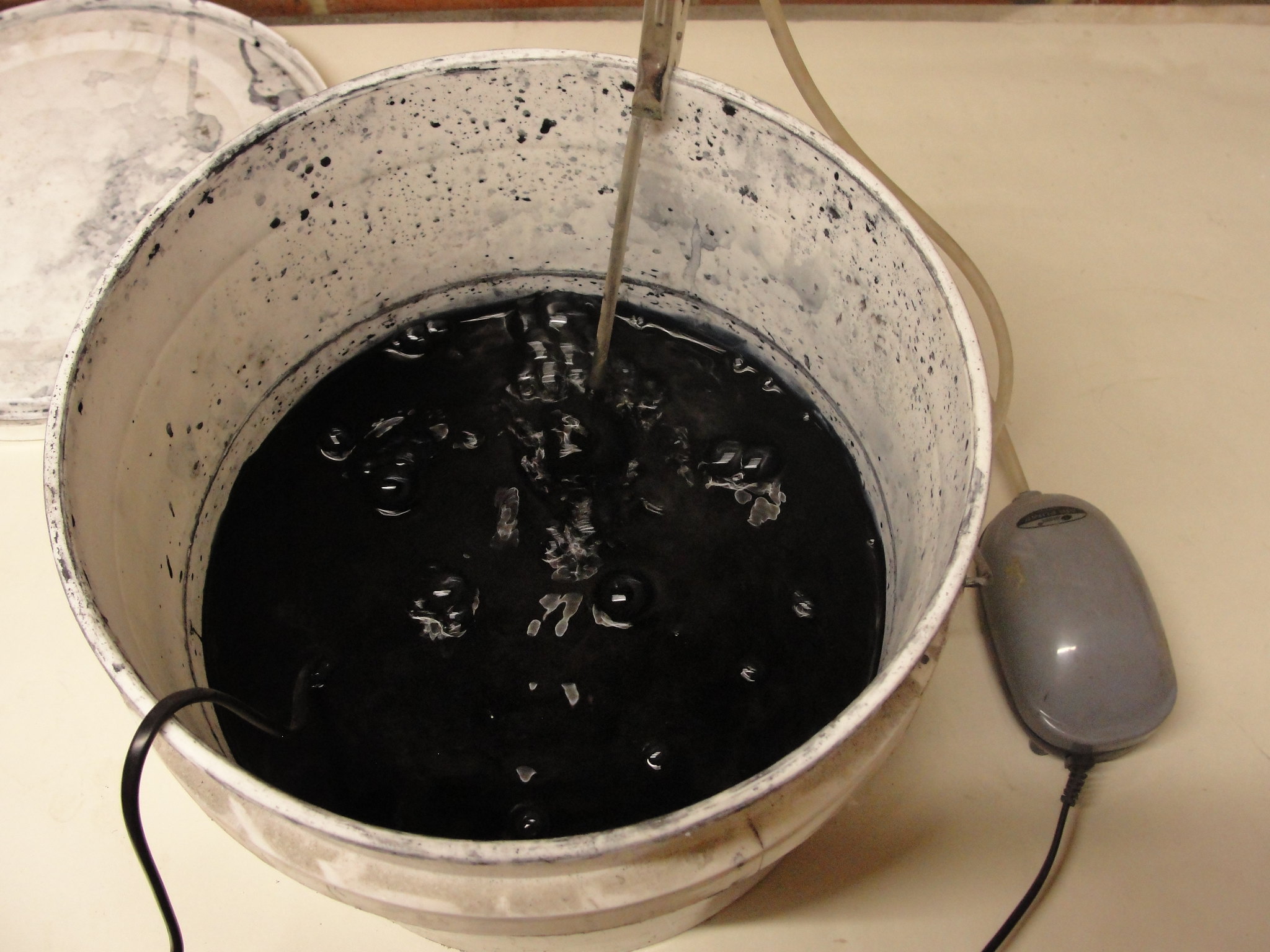 The last step is boiling in water to seal the surface. And the finished article ... 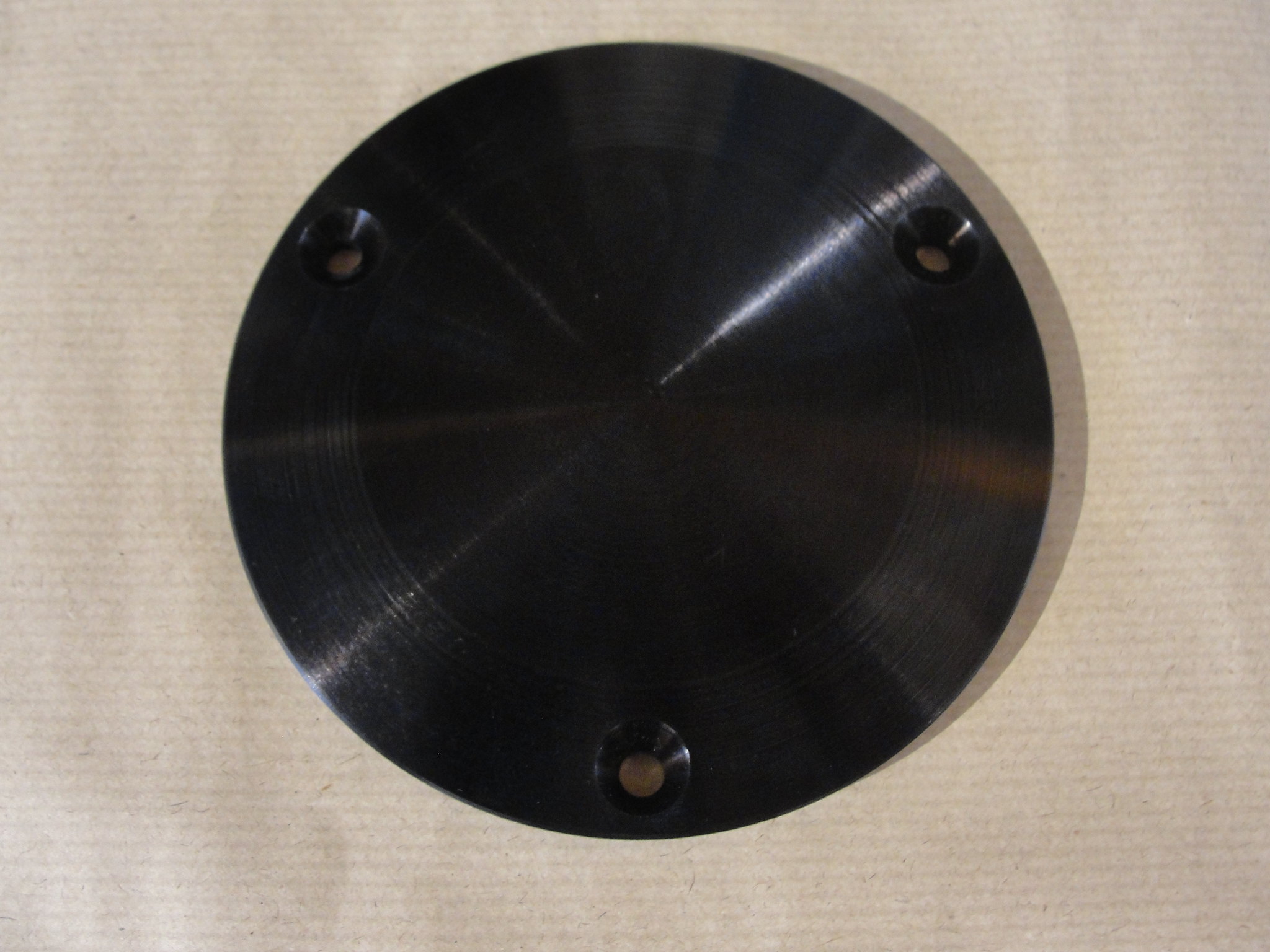 Jon |
|