|
|
Post by mouse on Jan 11, 2018 7:59:47 GMT 1
What a neat solution!
Mouse
|
|
|
|
Post by Tobyjugs on Jan 11, 2018 18:36:45 GMT 1
Lovely work, can i have one please 😊 I'm sure if you ask Pieter he will make you one  |
|
|
|
Post by Tobyjugs on Jan 18, 2018 21:13:51 GMT 1
Hello Chaps i have a few questions and would be very grateful if anyone could help me  Has any one ever measured the cooling water pressure of a 4LO engine? What pressure did you measure? How many rpm's was the engine making at the time of reading the pressure? Where was the pressure sensor installed. I want to learn about the operating parameters of these engines. My first idea was to just to stick a couple of old temperature meters somewhere next to the clocks. But now i am thinking about data loggers. Do they exist for our bikes? Are they expensive? whats out there to buy? |
|
|
|
Post by Tobyjugs on Jan 20, 2018 15:00:16 GMT 1
Back LashThis is something i would love to have an official explanation for. I always stick to the magic number 155 except for this build. I always measure the clearance between the primary drive and driven gear wheels and it always seems to vary in size even when the gear wheels are matched or not matched expressly by me to see if there is a pattern. I personally believe it does not matter as long as you have enough clearance. Because i do not know what the back lash number is referring to i always stick to the 155 rule. 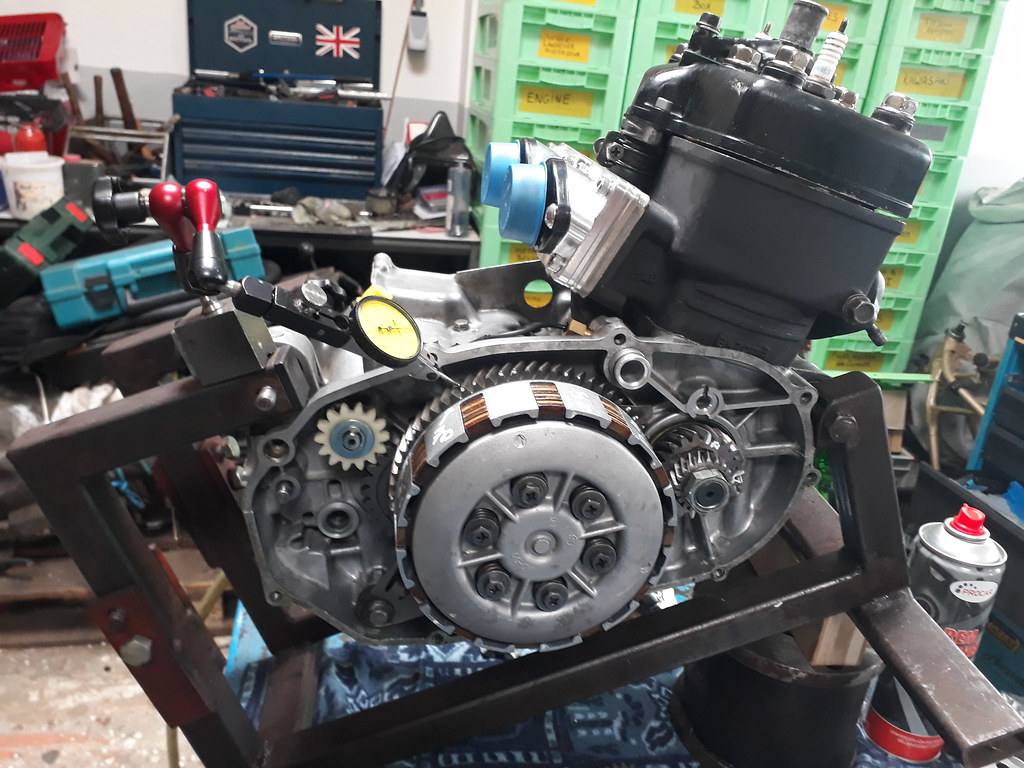 The primary drive gear wheel is marked in four places at approximately 90 deg apart and then the clearance is measured at each mark. 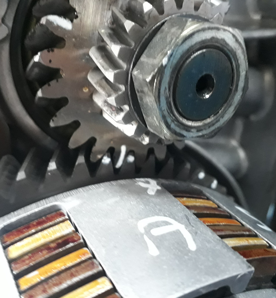 The primary driven wheel is continually turned in the same direction until it has made one complete turn. Every time one of the marked teeth of the primary drive gear wheel comes into contact with the driven gear wheel i measure and note the clearance. 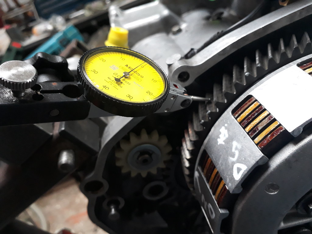 Taking lots of measurements instead of four builds up a good picture of the condition of the parts. I end up with 16 measurements which i use to find the average clearance. The two numbers used in this engine were 92 & 62B which added up to 154 the average clearance i measured was 0.08 mm which is tight compared to what i have measured on previous builds. I have another engine using straight cut gears from Nova which has an average clearance of 0.20 mm. Due to the small clearances found on this set up i will open the engine up after the first 100km to check for damage or wear. In my last post I asked some questions which i thought was pushing the boat out a bit as we are all enthusiasts and not R&D motorcycle engineers. I was hoping there might be some ex racers that might have some experience from his exploits over the years with either an RD or TZ.
|
|
|
|
Post by Tobyjugs on Jan 26, 2018 20:38:45 GMT 1
Received a package from Norbo today. This meant i could finish off my modified reeds. Can't wait to test them. I was told that EBC make and sell two different types of reed material, couldn't find any info over it. I have fitted new Yamaha reeds from Norbo 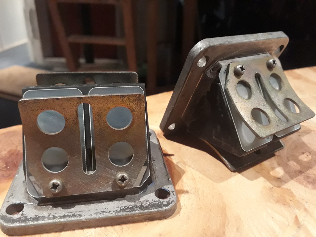 Next job is to fit the motor into the bike Kees uses. So bye bye 250 engine  |
|
|
|
Post by jon on Jan 27, 2018 9:11:59 GMT 1
Hi Tobyjugs, I too have always been interested in the subject of backlash.
I know we use the magic figure of 155 +/-1, but what does that really mean?
Do you think it may be a total backlash clearance maybe? Maybe it translates as 0.155mm?
If this were the case perhaps a bigger number translates as a ‘smaller’ gear. Then perhaps a tighter mesh would be lower numbers than the magic 155?
Unfortunately I have 5 sets of matched gears and 4 are 93 and 1 is 94. I don’t think this is enough difference to tell.
My other thought is that this was obviously backlash when the gears were new. They now have 30 years of wear. If the above is correct then a smaller backlash than 155 might actually achieve the desired effect.
This coupled with the fact mismatched gears by someone that didn’t care may well of increased wear.
That’s why I like your method of measuring as if we had a definitive lash in mm movement then we could be sure we had the correct backlash.
Edited as realised what type of DTI it was and had asked question I now realise answer to.
Jon
|
|
|
|
Post by Tobyjugs on Jan 27, 2018 19:31:35 GMT 1
Hi Jon i do not understand the 155 rule either. The engine above is 154 and the clearance is very small. I have measured a few now and there doesn't seem to be any logical pattern. I just note the lash numbers and the average gearwheel clearance so i can use the info for reference.
The DTI in the picture does not move in and out like a standard DTI. This one has a radial movement. if you look carefully you will see a ball on the end of the pointer this helps keep the movement constant to help an accurate reading. Very good for measuring gearwheel clearances. The drawback from this type of DTI is the small range of movement it can measure.
|
|
|
|
Post by simon998 on Jan 29, 2018 11:23:24 GMT 1
I need to stop reading this Toby, these are all things I didn't know I had to worry about when building my engine and now I'm crapping myself.
What're you doing to the reed block?
Great work as usual!
|
|
|
|
Post by Tobyjugs on Jan 29, 2018 22:44:40 GMT 1
I need to stop reading this Toby, these are all things I didn't know I had to worry about when building my engine and now I'm crapping myself. What're you doing to the reed block? Great work as usual! Thanks Simon for the kind remarks. I just want people to be aware of some checks to help build a balanced engine. The reed blocks have been fettled to reduce turbulance just like the V-force reeds. In the reed picture I forgot to cut the corners off the reeds at the base. I'm surprised nobody never commented. |
|
Mad Biker
Drag-strip hero
  We lead others try and follow.
Posts: 243
|
Post by Mad Biker on Jan 30, 2018 10:12:21 GMT 1
Tobyjugs. It looks like the small stiffening plate on the reeds has been fitted between the block and petal, but it should go between the petal and reed stop? Ignore if im wrong as its hard to see the pic from my phone!
|
|
|
|
Post by Tobyjugs on Jan 30, 2018 23:28:37 GMT 1
Tobyjugs. It looks like the small stiffening plate on the reeds has been fitted between the block and petal, but it should go between the petal and reed stop? Ignore if im wrong as its hard to see the pic from my phone! Thanks Martin i will look into this as i was not aware there was a stiffening plate. |
|
|
|
Post by Tobyjugs on Feb 22, 2018 1:20:33 GMT 1
Just a small update. I am now running the engine in and have done about 250 km. It has been very cold weather and with the two sensors fitted before and after the engine i have roughly a temperature difference of 10 degrees which i'm happy with but it's early days.
On a less positive note it has developed a small leak/weep of cooling water. I also noticed when warm the cylinder head bolts were a little loose. When they are cold they are at the correct torque. Sounds a bit strange, but i have never tried checking the torque with a standard head whilst warm. I have now re-torqued the cold engine at 30 n/m and i will measure how tight they are the next time the engine is warm.
I will carry on using the special head unless the leak gets too big. I want to build up a picture of how the head works before i put a standard head on to compare the differences.
For example: The last trip i ran at a steady 5000 rpm in top gear for 15 km's and the temperature of the coolant going into the engine was 40 C and the temperature the of the coolant after the engine was 50 C.
A little further down the road i was in 5th gear doing 4000 rpm and the temperature of the coolant going into the engine was 38 C and the temperature the of the coolant after the engine was 54 C.
The outside temperature was 0 C and just over 1/3 of the radiator is blocked off.
|
|
|
|
Post by Tobyjugs on Mar 28, 2018 22:12:47 GMT 1
Time for an update. The engine is run in but i am not to overjoyed with what i have been seeing with the temperature gauges. I removed the cover from the top of the radiator so the radiator was working fully. Above 5000 rpm the Temperature difference between in and out the engine is 2 degrees. Personally i think this is too small and it should be larger. The out going temperature of the water has always stabilised itself around 50 degrees or just under. Because the temperature difference is so small i am thinking there is too much flow over the cylinder head and not enough coolant going around the liner due to it's current design (easily modified). I also want to test it on the dyno but am worried about hot spots so i decided to put a standard cylinder head back on. When i removed the modified cylinder head i was surprised to find a light brown lacquer on the liner surface. I have seen this sort of thing lots of times on diesel engines but thats always been a bad combination of engine oil and fuel. This can't be the case with the 2-stroke engines. I do not know if it comes from the low or high temperatures. I tried to make some close up pictures but it was difficult with the flash. This is the best picture i made 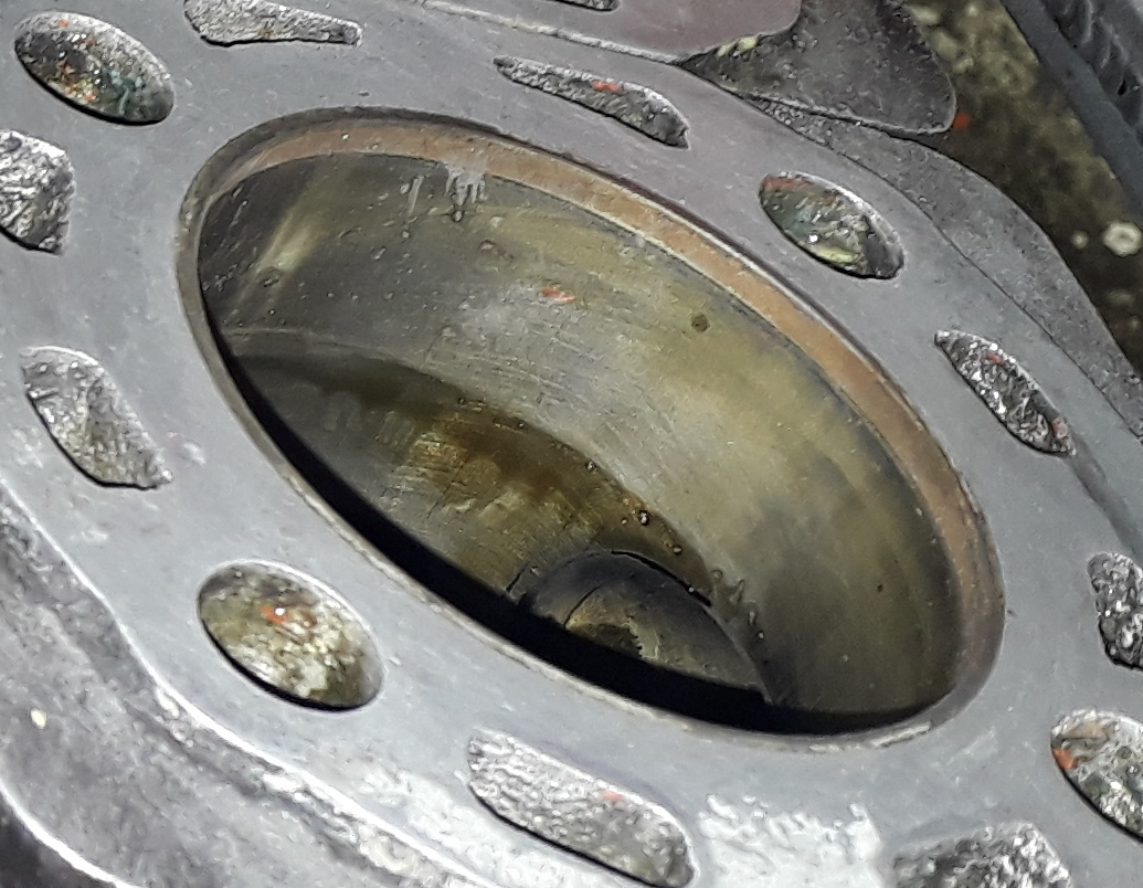 The dark line is oil but you can just make out a golden brown colour which get richer the deeper you look into the barrels. Cant wait to meet Pieter Smidt for a chat about this. So now a standard cylinder head is refitted with a yamaha head gasket. The squish is now 1.7 mm. I will now be able to compare the difference in cooling and feel safe when it go's on the dyno bank. Depending on the temperature results i will modify the special cylinder head to suit. At the moment it can flow more coolant over the head maybe short circuiting the barrels too much. |
|
|
|
Post by Tobyjugs on Mar 29, 2018 8:56:59 GMT 1
I forgot to ask last night. Has anyone else seen a brown discolouration before and did you know what caused this?
|
|
|
|
Post by 500RG on Mar 29, 2018 9:59:10 GMT 1
Blow by past a worn piston ring, high operating temperatures, poor oil.
|
|
|
|
Post by Tobyjugs on Mar 29, 2018 12:12:42 GMT 1
Blow by past a worn piston ring, high operating temperatures, poor oil. Thanks for your input. Have you seen this type of symptoms on your own engines The engine has done about 600 miles so far and I used motul 2 stroke oil.
I would have dismissed your remark about blow by but if you look carefully at the top of the liner you can see a distinct line which could be the second ring stopping the blow by.
I am thinking myself that the liner wasn't getting sufficient cooling as the lacquer could be seen to be more browner around the exhaust port area and lower in the barrel.
|
|
|
|
Post by 500RG on Mar 29, 2018 13:20:22 GMT 1
Hi,
No I haven’t experienced this with my own engines. I would rule out the oil as Motul is a respected brand, it is likely to be blow by past the rings.
|
|
|
|
Post by 500RG on Mar 29, 2018 13:24:03 GMT 1
Sorry, also meant to say that if your water temp is
Reading 50 I wouldn’t think that’s the issue, most 2 stroke
Bods say to aim for 50’s for an ideal running temp.
|
|
|
|
Post by Tobyjugs on Mar 29, 2018 14:17:57 GMT 1
Ok.
It's not the best time of the year to run an engine in but I have done a few times with the standard engine configuration without this lacquer on the liner surfaces. Now the cylinder head has been modified and I am thinking that there might be too much heat in the liner as more coolant can flow around the head and exit the engine. In the original configuration the cooling water must go into the liner area and back to the cylinder head before it leaves the engine.
Now a standard cylinder head is fitted to measure the cooling differences. I will be interesting to see if there is any more discoloring of the liner.
|
|
|
|
Post by 500RG on Mar 29, 2018 15:06:46 GMT 1
Does the modified head have a higher compression ratio / squish - could it be creating more pressure / greater compression and forcing the compressed mixture partly past the rings?
|
|
|
|
Post by Tobyjugs on Mar 29, 2018 15:50:46 GMT 1
Yes compression ratio is 12.5:1 (not so bad) but squish is 0.95 mm (thats tight) profiled to the piston crown.
|
|
|
|
Post by midlifecrisisrd on Mar 29, 2018 17:00:36 GMT 1
I forgot to ask last night. Has anyone else seen a brown discolouration before and did you know what caused this? Is it not just combustion residue not swept away by the rings There is always a coloured ring at the top (except on the +4 engine lol) but can't say I remember the colour What colour is the head domes Steve |
|
|
|
Post by Tobyjugs on Mar 29, 2018 20:47:24 GMT 1
I forgot to ask last night. Has anyone else seen a brown discolouration before and did you know what caused this? Is it not just combustion residue not swept away by the rings There is always a coloured ring at the top (except on the +4 engine lol) but can't say I remember the colour What colour is the head domes Steve Good point Steve but no. It really was a film i had to remove with some schotchbrite. Also a very good point about the cylinder head. the cylinder head was extremely clean with only some black residue at the outer edge of the Squish band, more so on the exhaust side. I also found the piston crowns very black for the amount of miles covered. I started off with 460 main jets and dropped them down to 440 and 2.5 turns out on the pilot screw to help the mid range stutter. Now i have put a bog standard cylinder head on its running to rich again so rather than mess around with the jets I put my TSA's on which cured this problem but i think i with have to go up two jet size's as it is acting like a scolded cat when it goes over the 7K mark. I took the opportunity to inspect the rings for signs of blow by and there is not much to see, so i can rule that out. With the standard head i am now getting a temperature difference of 3 degrees between in and out and the average out temperature is gone up to about around 55 degrees. This means more cooling around the cylinders as it cannot bypass that area or less flow due to the extra resistance. The 1 degree in cooling water difference does not sound much but i think it's quite significant. Next move will be to make sure the modified head seals better and take some measures to prevent the short circuiting of the coolant. Thanks to everybody for there help and if anyone has experiance of brown films building up on the cylinders walls i would like to hear about it. |
|
|
|
Post by midlifecrisisrd on Mar 29, 2018 20:50:51 GMT 1
It will be a few days before I can check but I have a pair of cylinders in a box that are only just run in
I'll look for a film at the bore top
Steve
|
|
|
|
Post by 4l04ever on Mar 30, 2018 11:59:39 GMT 1
The only brown film I have seen has been oil residue....
|
|
|
|
Post by Tobyjugs on Mar 30, 2018 14:39:43 GMT 1
The brown film is over the length of the barrel getting darker towards the bottom of the barrel and around the exhaust port.
|
|
|
|
Post by marrcel on Mar 31, 2018 19:45:00 GMT 1
I can imagine that running in piston and rings gives more resistance and wear. Combined with low coolant flow over the barrels it getting too hot. You can do an experiment with 2stroke oil. A few drops in the pancake on the furnace. Or in a temerature controled hot air oven. I guess any oil will laquer at 300C.
|
|
|
|
Post by Tobyjugs on Apr 1, 2018 12:29:34 GMT 1
I can imagine that running in piston and rings gives more resistance and wear. Combined with low coolant flow over the barrels it getting too hot. You can do an experiment with 2stroke oil. A few drops in the pancake on the furnace. Or in a temerature controled hot air oven. I guess any oil will laquer at 300C. That's one way of putting it Marrcel. |
|
|
|
Post by Tobyjugs on Apr 6, 2018 13:20:25 GMT 1
Yesterday took the bike to the dyno-bank to adjust the fuelling.
At first everything was going good except for the clutch slipping when the oil was cold. The bike was making good power but had a very bad stutter around 6k. Tried for a while too cure this but not much happened. The carbs needed to go one jet higher to make sure the mixture was safe. I decided to change the standard reeds for the modified set and the modified inlet manifolds with the thought of one or two slight adjustments and thats it.
It became very apparent on the next run the stutter had disappeared, but the whole set up was running lean. The first thing i noticed was idle speed had gone from 1200 to 1500 rpm. and not much changed on the dyno-curve.
The resin reeds were swapped for some Boysen trapdoor reeds and the curve stayed the same even when 500 main jets were fitted and other pilot settings were tried.
For the last run of the night 6mm spacers were fitted between the block and the reeds and 520 main jets were fitted. This made the bike idle even faster and the peak horsepower dropped by 2 or 3 hp. The carburation was still too lean.
I have been giving it a lot of thought today as the carbs should be good for 70 PK. I don't think the carbs could deliver enough fuel. This was using a 51K needle and 345 P0 needle jet.
The first thing i am going to check is how i adjust the float height. I could be making a constant mistake here and setting the fuel level in the bowls too low?
I might add some oil to the filters.
The standard carbs should be good for 75 Pk does that sound correct?
If i change the size of the carbs what do you recommend and why?
Is 28mm PWK's big enough for 80 PK?
|
|
|
|
Post by midlifecrisisrd on Apr 6, 2018 16:11:48 GMT 1
If you are up to 520 jets I'd say the carbs ain't working
I've seen standard carbs do 71 horse on a ypvs but lc is a different beast
The pwk's should be fine, running them on my 385 without probs
My worry going bigger is you will lose the low end
Steve
|
|