|
|
Post by tsa on May 3, 2015 18:11:37 GMT 1
I have sent 2 sets to Holland I believe.
|
|
|
|
Post by Tobyjugs on Aug 2, 2015 10:00:43 GMT 1
Hello chaps its been a while, finally got something to write about. After modifying the pistons and seeing what effect this had, and realising the cylinders were not scrap (thanks for the advice Kenny) it was time to try to sort out the port timing. The porting work was done by Pieter Schmidt. Had a little bit of a chat with him and explained i did not want this Gs 550 feeling and also not a flat out race tune. I gingerly put forward Kenny's suggestions which he listened to and replied with the answer i will see what i can do. Due to the fact i had to work away for about 10 weeks it's taken a long time to get it all together. Last Friday i had a day off and spent all day adjusting the carbs. At last it felt like a 2stroke again and it caught me out a little when the front end went up in 2nd gear as i was not expecting it. (landed a bit wobbly). I ended up fitting 380 main jets and the pilot jet was 27.5 which i had to ream out as i had nothing bigger and the bike was going on the dyno on Saturday. It was put on the dyno and it achieved 66 hp, 9hp more than altering the pistons and 15hp more since the first measurement. 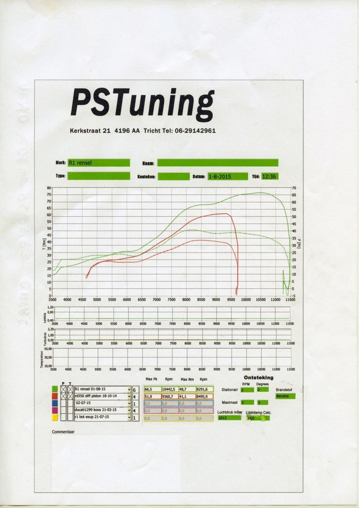 Pieter told me i now have to put some bigger carbs on. Not quite sure what i want to do now. Try to rescue the power valves, get the exhaust sorted, put some decent pistons in it, or first listen to the advice of the tuner. 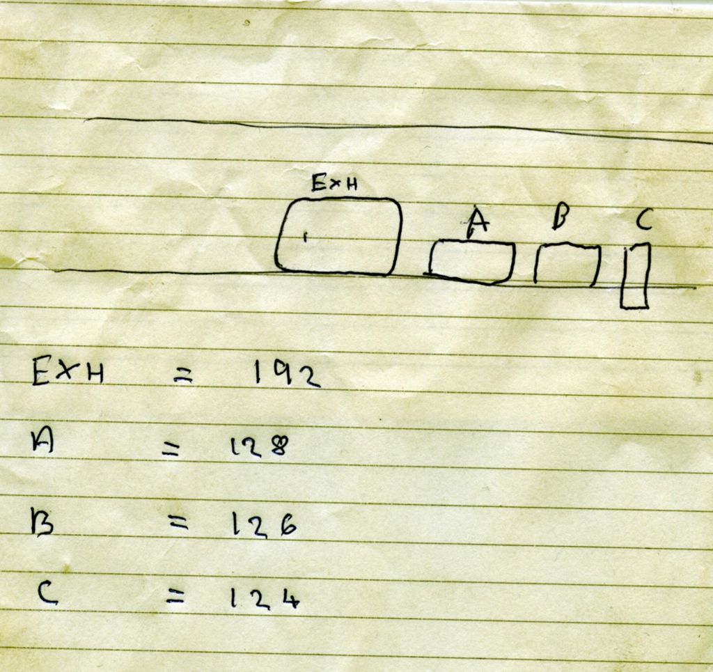 The the duration of the transfer ports are staggered to give a smother power transition. |
|
|
|
Post by tsa on Aug 2, 2015 16:40:24 GMT 1
What were the changes he made bud? Looks better now than before thats for sure.
|
|
|
|
Post by Tobyjugs on Aug 2, 2015 17:47:19 GMT 1
I did not explain it very well, he has changed the port timing; Exhaust duration open/closed was 184 deg now is 192 deg Transfer ports A duration open/closed were 124 deg they are now 128 deg Transfer ports B duration open/closed were 124 deg they are now 126 deg Boost ports C duration open/closed were 96 deg they are now 124 deg (I have two small ports instead of one as on a standard YPVS see pictures in earlier post) The last picture i posted was a simple drawing of the port map, I spent almost two tanks of fuel and a lot of fiddling with the carbs just to make sure they were not to lean, and i think if they were set up professionally the curve might have been better. I will now do another test with these carbs on it 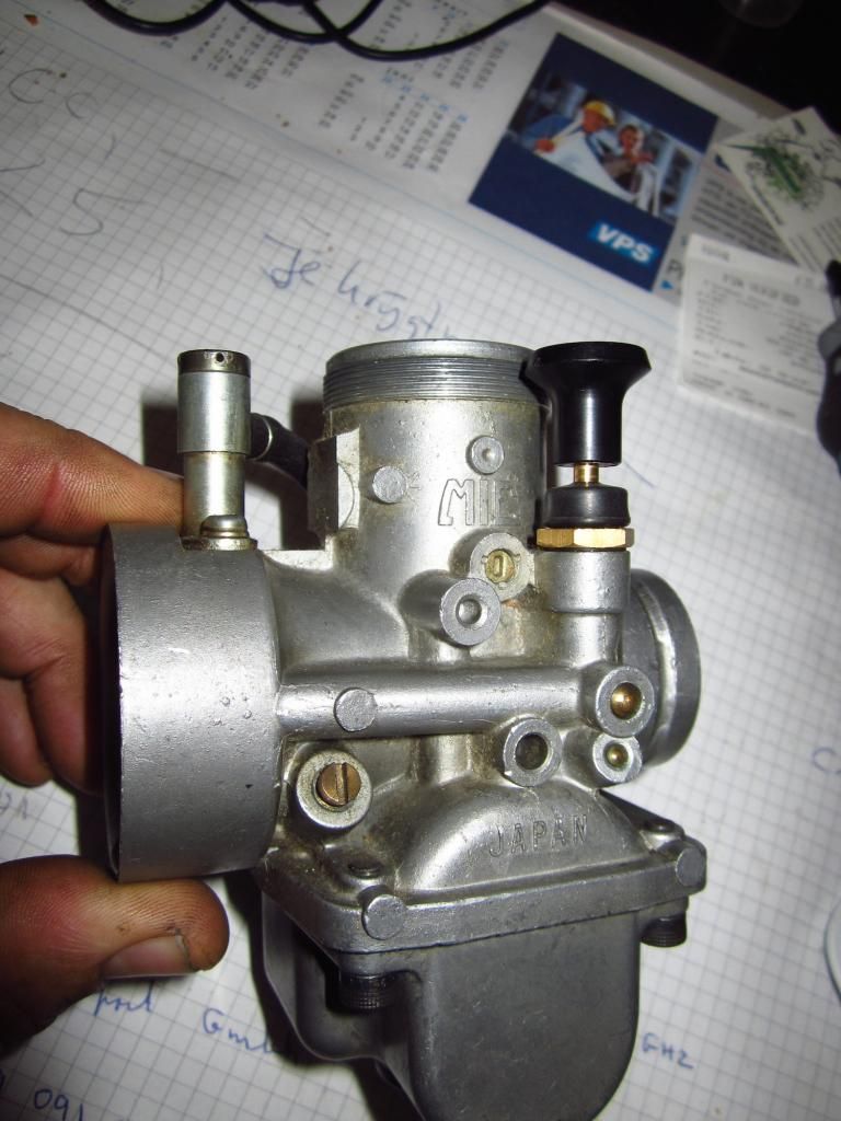 I just have to find a guide on how to set them up as they are power jet carbs. So if anyone has some advice or a link please share. |
|
|
|
Post by Tobyjugs on Feb 20, 2016 18:34:13 GMT 1
It's been a while and i am still busy with it. Still have not fitted the bigs carbs as first planned. Due to the remarks of Kenny and Pieter about the JL's i decided to first go for the pipe's after speaking to Kenny it became very clear that some special pipes would take a long time because he is so busy so i ordered a standard set of 350 pipes for my normal LC from Kenny and put my trust into Pieter and aksed him to make some pipes for this engine. Initially they should have been finished end of November beginning of December. They were finished yesterday Here They are; 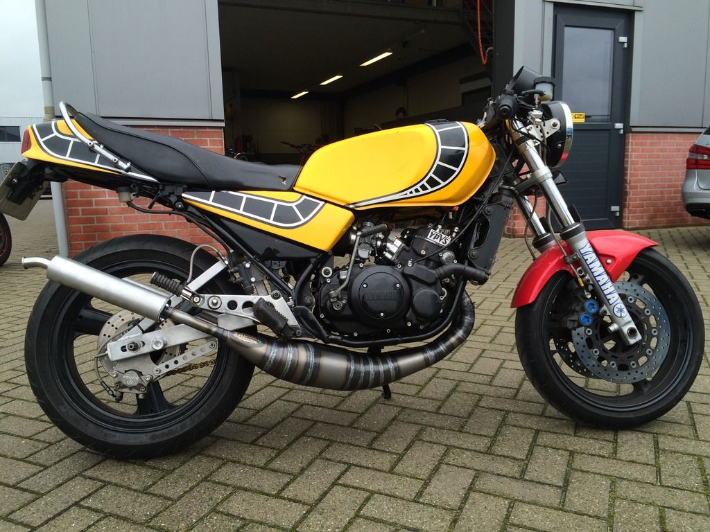 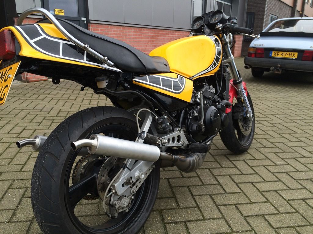 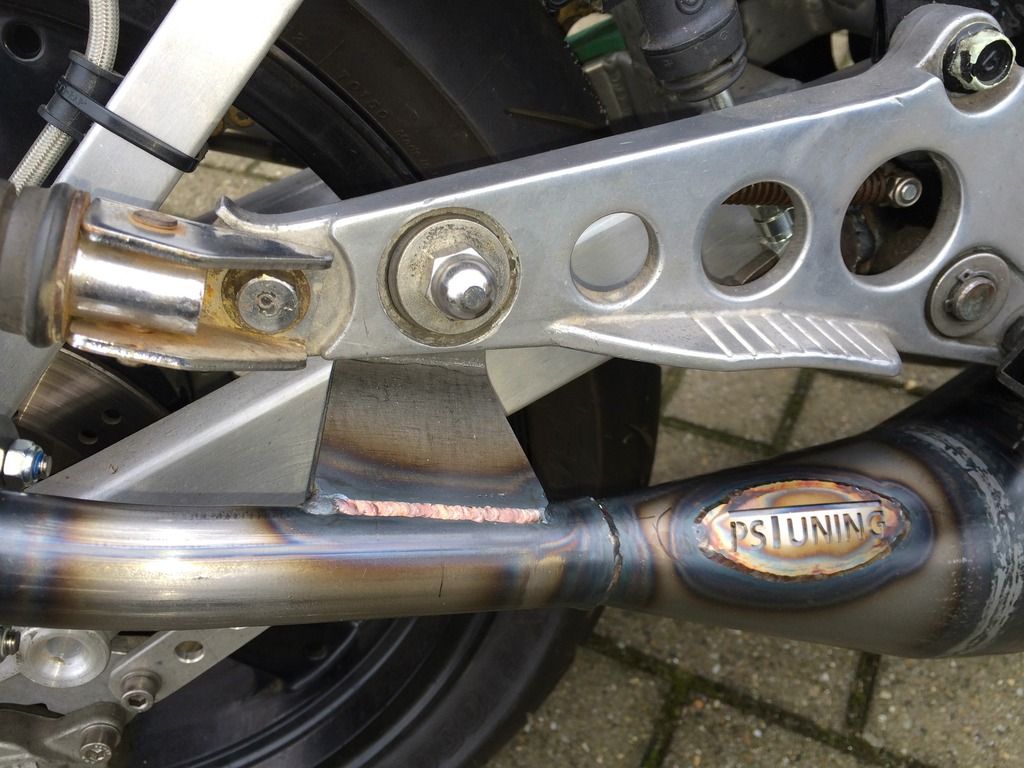 They are very tight down the middle of the engine so i do not have a problem with side stand. I wanted a classic black and silver look but it seems a shame to hide the discolouration. The baffles were made to keep the noise down due to circuit regulations, but i will have some shorter ones for posing value and to make sure my neighbours know i'm home ha ha He has also made them adjustable at the front to make them less peaky if i want (did not really understand that bit i just nodded) I ended up waiting most of the day before we could put it on the dyno as he was very busy with people coming in asking him to do small porting jobs on the spot. With the first initial run it was running too weak. The second run with 430 mains in it was still running too weak and time was up, so i will have to wait until Tuesday before we can go further. At the moment peak horse power is 71 pk which i am happy with as i almost threw away the cylinders. I would just like to add i don't know where peak power is. |
|
|
|
Post by Tobyjugs on Feb 20, 2016 18:40:41 GMT 1
Oops i managed to post twice
|
|
|
|
Post by lrcarl on Feb 25, 2016 9:21:10 GMT 1
if effort = reward should work out fine
would be good to see them pv's working
carl
|
|
|
|
Post by Tobyjugs on Feb 25, 2016 23:39:28 GMT 1
Thanks for the remark Carl. I really enjoy playing with this engine seeing what happens every time something is changed.
|
|
|
|
Post by Tobyjugs on Sept 29, 2016 4:18:23 GMT 1
A short update. I had a bit of an issue with what looked like a lean carb set up, but it turned out to be the compression ratio was too high. After measuring the volume in the combustion space with oil it turned out to be almost 16:1.
So i removed the head and barrels in preparation for machining the cylinder head to the correct size.
Whilst the top of the engine was stripped i noticed that the axial clearance on one of the big ends was out of limit.
The crank was removed and i pressed the crank back into place and welded it slightly to stop it moving (hopefully) This was all done in the spring of this year and i have now dropped the head off to be machined.
|
|
|
|
Post by Tobyjugs on Apr 10, 2017 22:14:06 GMT 1
I thought I had better update this thread. Here is a dyno chart from the engine with too much compression 16:1  It is the green line It is the green line
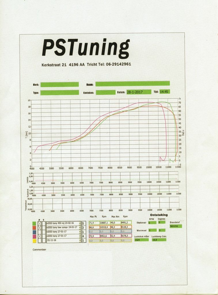
The top end was stripped and PS Tuning rebored the cylinders to 68.25mm and the cylinder head was re-profiled to suit the new Wossener pistons. Due to the strange wear pattern I have seen in the liners, I also asked him to check and true up the barrels in relation to the aluminium out side. (these barrels have been re-sleeved i and never checked for accuracy)
Here is the head with to small a combustion chamber. Also you can see that the squish band was also a little bit too wide. 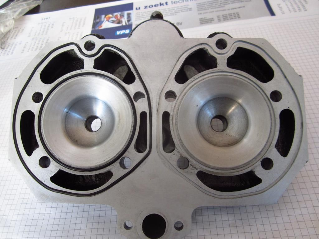
Here it is with the combustion chamber adjusted for the correct compression ratio. 13:1 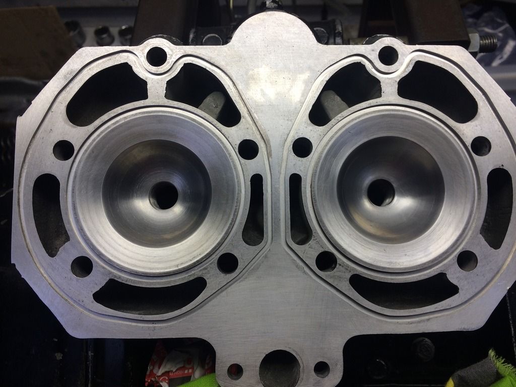
Below is a picture of the new Wossener pistons fitted into the newly honed barrels. 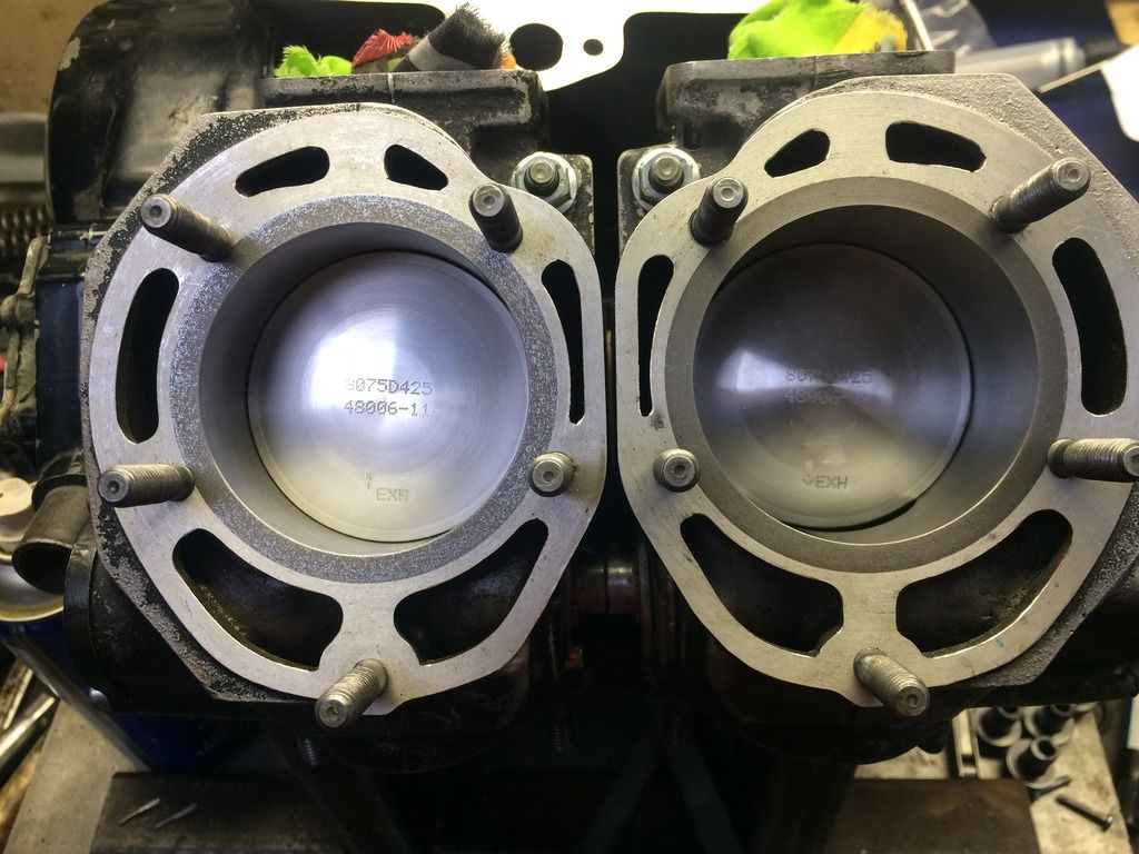
If you look at the outside edge of the piston crown you will see it is a slightly different colour, this is because the outside edge (almost like a lip) of the piston crown has been removed to keep the profile of the piston uniform and help keep the port timing the same.
This was built up and run in for about 450 miles and was put on the dyno to check the power, this can be seen as the red line. I was thinking I would loose more power once the compression ratio was corrected but it was only about 5hp so I was very happy with that 
|
|
|
|
Post by 4l04ever on Apr 11, 2017 8:07:03 GMT 1
Looking good. Keep up the good work! :-)
|
|
|
|
Post by Tobyjugs on Apr 11, 2017 8:16:16 GMT 1
Looking good. Keep up the good work! :-) Thanks to you Rob. Now you know why i keep ordering so many gaskets from you.  The engine is a bit further on than this and i will update some more when i feel like using my flap top. |
|
|
|
Post by Tobyjugs on Nov 11, 2017 22:25:46 GMT 1
I didn't know if to start a new thread, but decide to add it to this one, Does anyone know what this is? 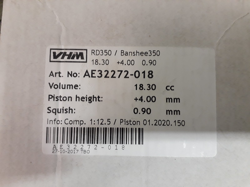 |
|
|
|
Post by Tobyjugs on Nov 12, 2017 9:12:20 GMT 1
I'm a bit surprised nobody tried guessing what this could be  |
|
|
|
Post by jon on Nov 12, 2017 9:53:49 GMT 1
I'm a bit surprised nobody tried guessing what this could be  Tobyjugs, is it a removeable dome for a cool head with a stroker crank? I've seen a picture of your modified standard head, but can't seem to find it. Jon |
|
|
|
Post by lrcarl on Nov 12, 2017 10:27:13 GMT 1
Are they for your modded stock head?
Carl
|
|
|
|
Post by midlifecrisisrd on Nov 12, 2017 11:34:18 GMT 1
As above
Stock head modified to take domes 😁
Steve
|
|
|
|
Post by Tobyjugs on Nov 12, 2017 12:24:22 GMT 1
Yes at last everything is finished so i can build the engine back up and test it. 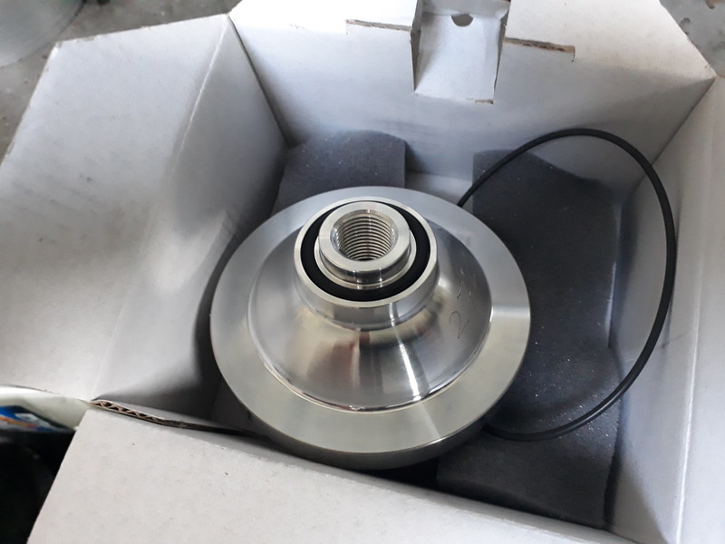 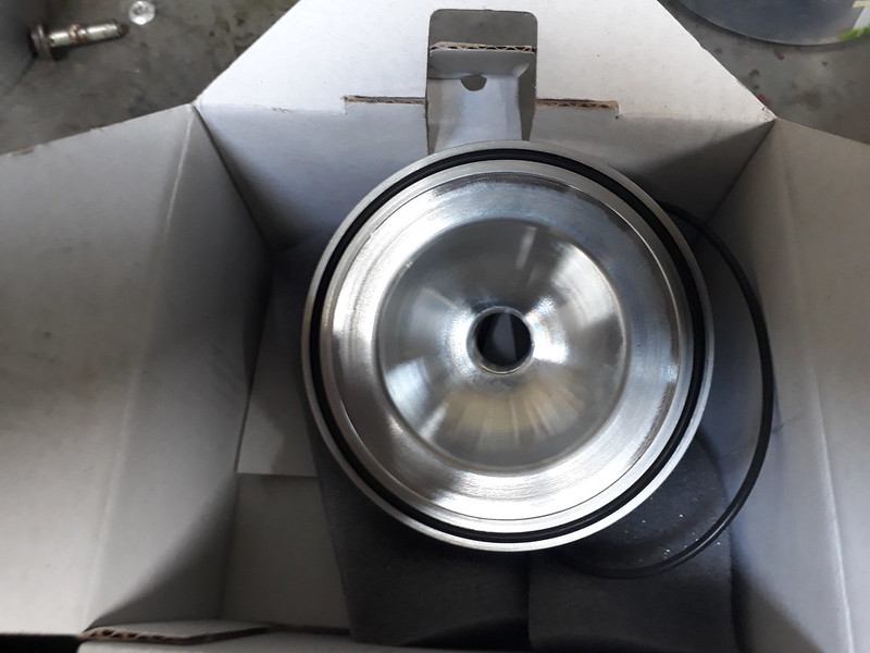
I was going to pin the dome but was told the pinch exerted on the domes from the cylinder head bolts will hold them tight. 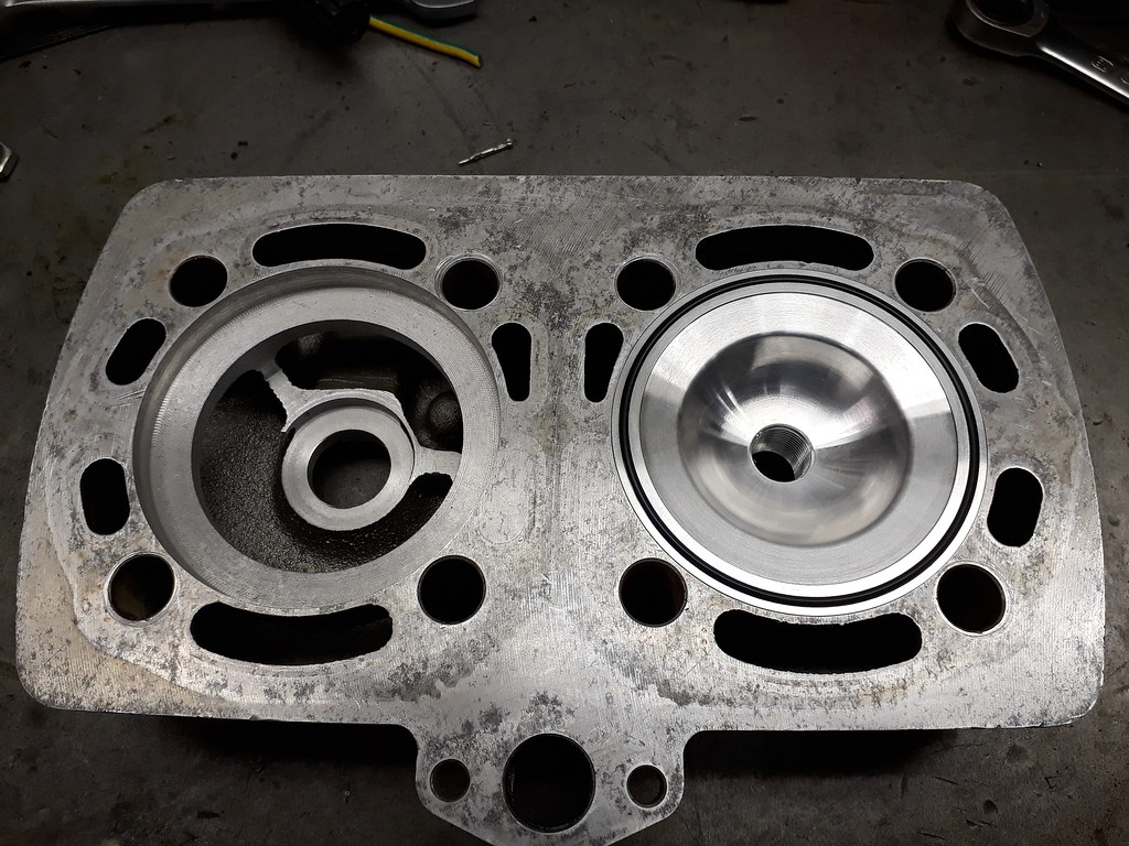 |
|
|
|
Post by Tobyjugs on Nov 12, 2017 12:34:34 GMT 1
I'm a bit surprised nobody tried guessing what this could be  Tobyjugs, is it a removeable dome for a cool head with a stroker crank? I've seen a picture of your modified standard head, but can't seem to find it. Jon Hi Jon it was a Standard 250 head now modified for a normal 350 engine. The +4 means the very top of the piston sticks out 4mm above the top of the liner with a standard 0.5 mm gasket if you look carefully at the info it also give the piston size which is 1.5 mm oversize. |
|
|
|
Post by Tobyjugs on Nov 12, 2017 19:54:33 GMT 1
Time for a bit of a story. About 3 or 4 years ago i bought a compete engine for about fifty euros for spare parts, after a basic inspection i decided to just put it in my other bike and run it. I never opened the engine up but could see that some one had attacked the engine with a file or dremmel to fit larger YPVS and it looked real rough. The reeds did fit with the aid of a spacer. I noticed after some usage it was using about 5 tanks of fuel before the oil light come on. I had checked the pump and set it up when i installed the engine. Eventually i took the pump off and sent it to Arrow. In the mean time i just used pre-mix. The engine sounded rattly but still felt pretty lively and i used it as a reserve engine swapping it in and out my hybrid bike whilst i was playing with the engine in the above thread. I put it on the dyno to set it up correctly for a track day holiday in Spain and it was making 60 hp not bad considering it was a little abused and i had driven almost 4000 km on it. I decided to strip it down after Spain and rebuild it. When i opened it up i was happy to find it had +0.50 mm pistons in it and the hone marks were still visible (happy days i thought). When i took the the barrels off and had a good luck it was another story. The running surfaces of the barrels looked good but where the exhaust ports are oval it looked like some one had chipped them square and it looked deep (oh blimey). Eventually the barrels had to be rebored to +1.50 mm to get rid of these marks. I did take some pictures to post but i lost them somehow. I have seen similar pictures posted on this site i think by midlifecrisesrd. Hi Steve if that was you any chance of posting them on this thread? for other people to see. The engine was stripped down and everything looked well put together. All the gearbox bearings were completey worn. The axial play for the con rods was good. I removed the crankshaft and pressed it apart, the pressure needed was high so this was a good sign. Before i started using the press i had to remove the two outer main bearings. To my surprise when i stood the crank upright to remove the top outer main bearing the lower outside main bearing just fell off and vice verse. The same thing happened to the inside bearings once the webs were pressed off. Here are some pictures of the old crank. 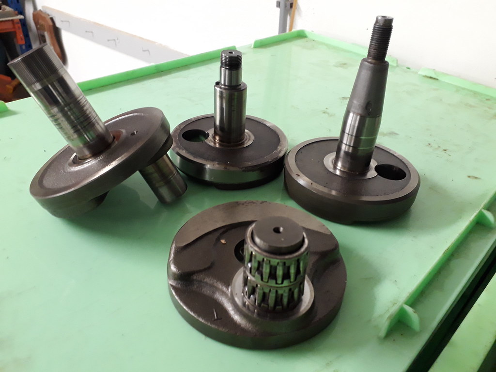 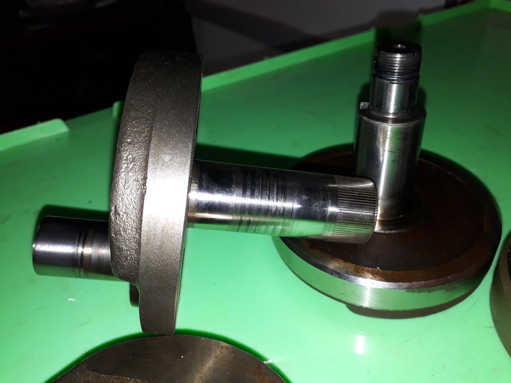 I have used a new crank and will put the other one back together but first i need to check it properly. |
|
|
|
Post by Tobyjugs on Nov 13, 2017 18:45:31 GMT 1
I have a chariot inlet manifold lined up for this engine. I like this manifold because it has aerofoil built into the manifold. After talking to my tuner about the manifold the plate with the aerofoil was discarded (didn't want to ruin it) and the main inlet manifold was bored out round and bushed to reduce the internal diameter to suit the standard 26 mm carbs This is the plate which bolts onto the body of the inlet manifold. The plate has the balance tube and aerofoil machined into it. 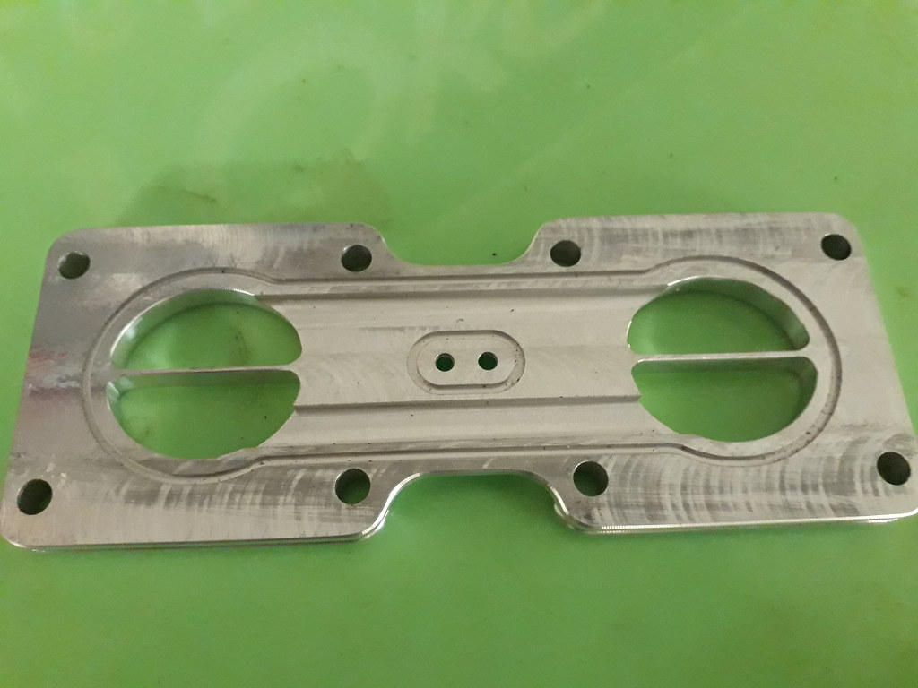 Information about balance pipes was hard to find so a 9.5mm diameter hole is now the size for the new balance pipe. 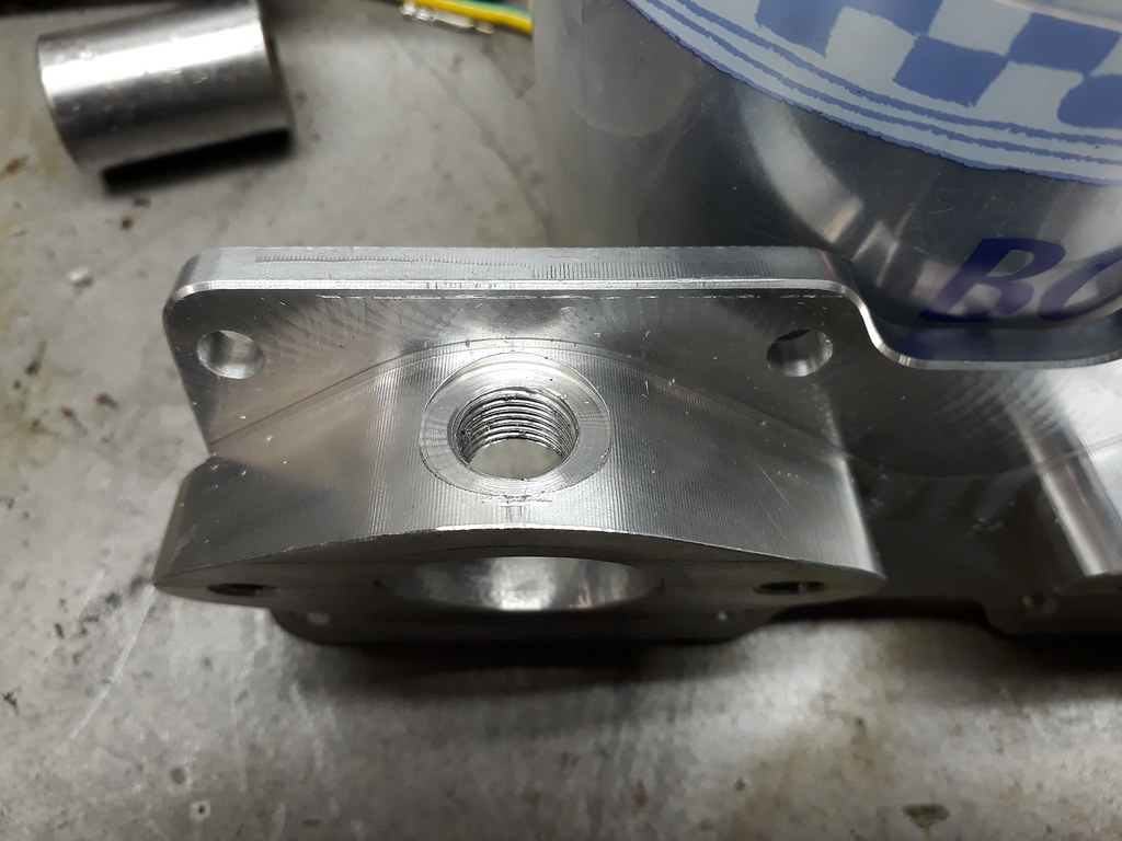 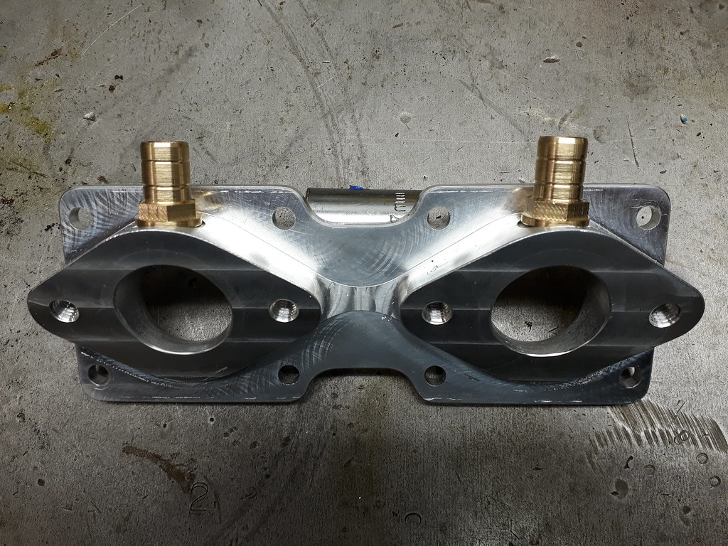 |
|
|
|
Post by Tobyjugs on Nov 14, 2017 22:43:19 GMT 1
I am about to start building the engine up but before i do i check everthing one last time. Tonight i checked the cylinder head for flatness. It turns out that it is slightly banana shaped, low in the middle and high on the out side edges. How ever it is not twisted. 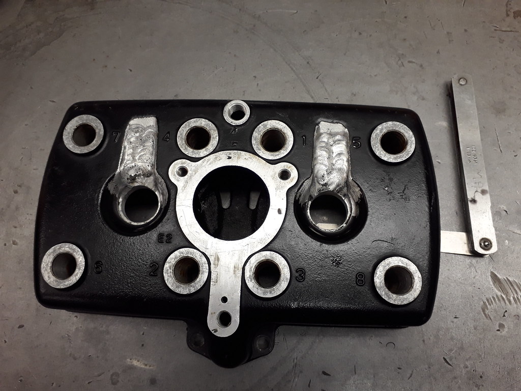 The difference between the middle and the outside is roughly 0.08 mm. A 0.05 mm feeler fits under loosely and 0.10 mm does not fit. I should have checked the head before i started the modification. To be honest i don't think it matters as the domes will be pulled tight and square on the barrels and the little room which is left will be filled with sealant. (Thats the plan ha ha) |
|
|
|
Post by jon on Nov 15, 2017 7:52:05 GMT 1
Tobyjugs, will the spark plugs seal properly?
That welding looks like it goes right to the edge.
I thought there was a small flat for the compression washer on the plug to sit?
Jon
|
|
|
|
Post by stusco on Nov 15, 2017 8:19:47 GMT 1
Tobyjugs, will the spark plugs seal properly? That welding looks like it goes right to the edge. I thought there was a small flat for the compression washer on the plug to sit? Jon The plugs will seal on the domes the domes will seal on the under side of the head |
|
|
|
Post by jon on Nov 15, 2017 8:48:38 GMT 1
Tobyjugs, will the spark plugs seal properly? That welding looks like it goes right to the edge. I thought there was a small flat for the compression washer on the plug to sit? Jon The plugs will seal on the domes the domes will seal on the under side of the head That makes sense. Looking back they do look too big for 14mm. Jon |
|
|
|
Post by midlifecrisisrd on Nov 15, 2017 9:13:15 GMT 1
The non flat head should be fine
As the high pressure areas are sealed by o rings and the water jacket with gap filling silicone I foresee no issues.
Fingers crossed
Steve
|
|
|
|
Post by Tobyjugs on Nov 15, 2017 19:24:58 GMT 1
The non flat head should be fine As the high pressure areas are sealed by o rings and the water jacket with gap filling silicone I foresee no issues. Fingers crossed Steve Yes Steve that' the plan |
|
|
|
Post by Tobyjugs on Nov 15, 2017 19:26:21 GMT 1
The plugs will seal on the domes the domes will seal on the under side of the head That makes sense. Looking back they do look too big for 14mm. Jon Jon when I get home I will make a picture for you |
|
|
|
Post by jon on Nov 15, 2017 20:30:44 GMT 1
I've never had a cool head before, so haven't really studied them.
I wonder if part of the reason they cool better is that the combustion chamber has a thinner wall, and so transfers heat to the coolant quicker?
Jon
|
|
|
|
Post by Tobyjugs on Nov 15, 2017 23:00:30 GMT 1
I've never had a cool head before, so haven't really studied them. I wonder if part of the reason they cool better is that the combustion chamber has a thinner wall, and so transfers heat to the coolant quicker? Jon Hi Jon i can show you a cool head dome as well. Here is a picture of the top part of the insert loose in the head. 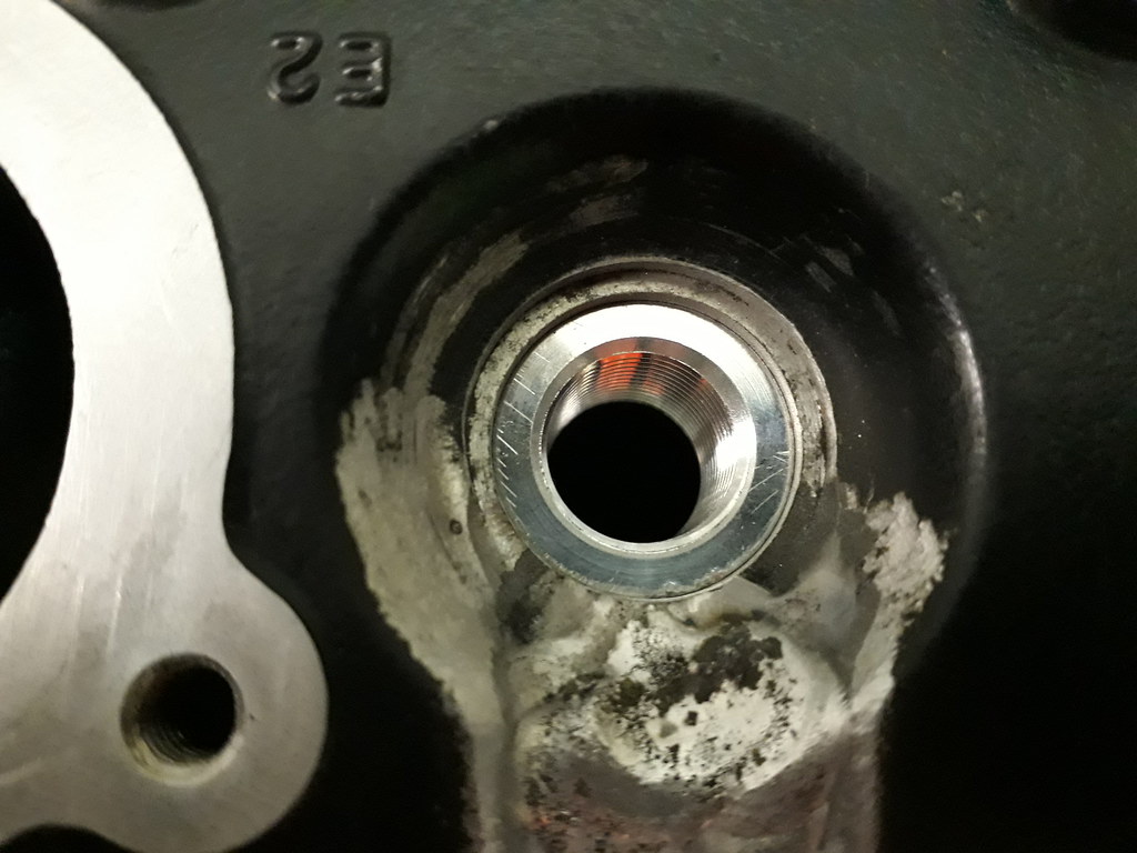 Here is a picture showing how the plug fits in the dome 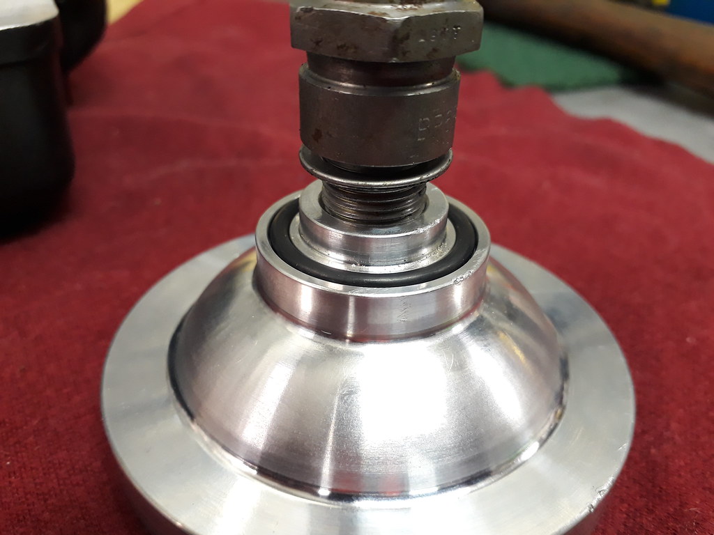 Here is a dome from a cool head. Due to the stepped construction the surface area of the dome is much bigger which means better cooling. I do think the position of the temperature sensor can be a bit misleading as it's at the entrance of the cooling water into the cylinder head. 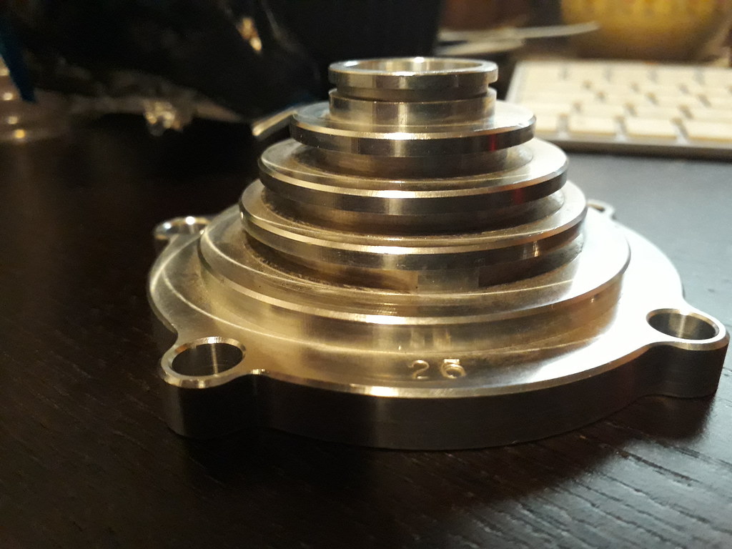 |
|