|
|
Post by dusty350 on Nov 29, 2018 8:25:18 GMT 1
Forgot to add, I was going to experiment with putting 1104 in a small syringe and apply it that way, but just went with my usual way of doing it in the end (couldn't find the syringe !!) Dusty  |
|
|
|
Post by alankelly on Nov 29, 2018 9:54:23 GMT 1
Hi Dusty
Thanks for the tips and advice. You are a star👍
Catch up again soon
Best wishes Al
|
|
|
|
Post by Tobyjugs on Nov 29, 2018 10:44:40 GMT 1
I use a small paint brush to apply the sealant. The loctite sealant you mentioned is rubbish in my opinion. I have used it many times. If you do want to use a Loctite product I would suggest 5910. Seals very well but it will probably be difficult to split the engine the next time.
|
|
|
|
Post by dusty350 on Nov 29, 2018 10:54:58 GMT 1
The other option is the nozzle you get with small tubes of automotive silicon sealant. If you can find a tube that fits the top of the Threebond, that would work well  Dusty |
|
|
|
Post by 4l04ever on Nov 29, 2018 11:00:10 GMT 1
I use a brush to apply the sealant to get a good even layer all round.
|
|
|
|
Post by alankelly on Nov 29, 2018 11:15:07 GMT 1
Hi guys
Great tips
Think I will try Dusty’s tip and use a nozzle on the end of the tube then where needed use a brush
Again many thanks for the advice guys
Best wishes Al
|
|
|
|
Post by alankelly on Nov 29, 2018 17:46:57 GMT 1
Hi Dusty
Great tip
Got a load of spare silicon application nozzles from work and they screw directly onto the tube of threebond 👍👍👍
|
|
|
|
Post by dusty350 on Nov 29, 2018 19:16:02 GMT 1
Dusty
|
|
|
|
Post by alankelly on Nov 29, 2018 21:08:15 GMT 1
Hi all Well thanks to all for all the top tips on using Threebond 1104 I used a fresh silicon nozzle as per Dusty's suggestion (Thanks Dusty) and the sealer was a doddle to apply 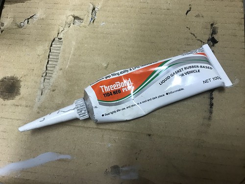 IMG_5790 IMG_5790 by Alan Kelly, on Flickr And then where necessary moved it about with the brush (Thanks 4l04ever) to ensure an even surface that covered all sealing surfaces, and then put it all together with the new Yamaha crank seals 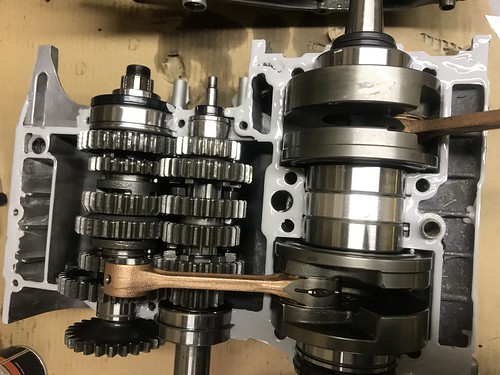 IMG_5786 IMG_5786 by Alan Kelly, on Flickr Looking at the result pretty confident that this area is now well and truly airtight Now plan to get the rest together over the next few days using genuine Yam' base and head gaskets and maybe possibly use a "Al's design" for the intake gaskets build (will let you know my idea once I have made it) and then retest for leaks :-) Again thanks to all for all your help. Best wishes Al. |
|
|
|
Post by dllc on Nov 29, 2018 21:15:03 GMT 1
You'll have to start marketing all the "Al designs" parts.
Build looking great.
D
|
|
|
|
Post by alankelly on Nov 29, 2018 21:27:09 GMT 1
Hi D
Thanks for the compliment
To be honest I just enjoy making the bits just for myself as a challenge to myself on how to improve an original concept (like my mod to add a second needle roller assembly to the shift cam drum so that it is no longer rotating in a plain bore) or design and then make from scratch something unique like my hydraulic clutch.
Catch up again soon
Best wishes Al.
|
|
|
|
Post by dusty350 on Nov 29, 2018 21:53:46 GMT 1
Safe to say it's unlikely you'll get a leak between the case halves  Looking good Al, another job "jobbed" !! Dusty |
|
|
|
Post by alankelly on Nov 30, 2018 21:02:24 GMT 1
Hi all Been busy in the shed again tonight and wanted to share an idea During my first build when leak testing I had a small leak on the inlet ports (The gasket seal between the barrel and the spacer) Looking at the design of the ports and as I am planning to add a 6mm reed spacer, I was going to try and replace the paper gaskets with an O ring located in a machined groove in the reed spacer but Mr Yamaha has not left me enough room. And to add to the problems the 4 M6 holes are way off center on the R/H barrel that totally scraps that idea :-( So had another thought, as I am fitting the spacers, I have sourced some fuel resistant Nitrile rubber, and have modified the spacers by bonding the sheet of 1mm sheet to either side (as the nitrile rubber on its own is too flimsy to make a gasket) And then cutting the required apertures etc, 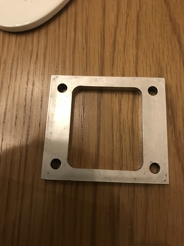 IMG_5796 IMG_5796 by Alan Kelly, on Flickr 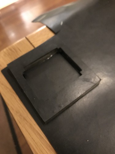 IMG_5806 IMG_5806 by Alan Kelly, on Flickr 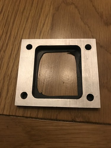 IMG_5805 IMG_5805 by Alan Kelly, on Flickr 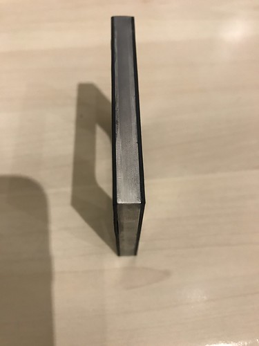 IMG_5801 IMG_5801 by Alan Kelly, on Flickr 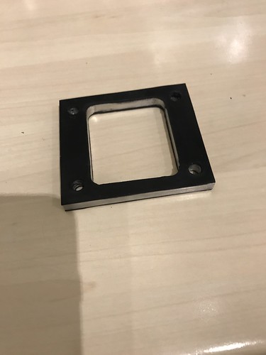 IMG_5799 IMG_5799 by Alan Kelly, on Flickr Plan now is to (As the barrels are off) is to lightly "lap" the inlet port gasket face to ensure the face is completely flat, then fit 4 M6 studs to remove the possible issue of stripping out the delicate (And on my barrels very "tired") m6 threads, and then fit without and silicon and then leak test. Will update all with the result once tested but any comments always welcome.. Catch up again soon. Best regards Al. |
|
|
|
Post by Tobyjugs on Nov 30, 2018 21:59:47 GMT 1
Rob on this forum makes gaskets for are bikes from a similar product.
|
|
|
|
Post by 4l04ever on Dec 2, 2018 0:33:10 GMT 1
Rob on this forum makes gaskets for are bikes from a similar product. Yes, I made some from 1mm Viton... |
|
|
|
Post by alankelly on Dec 7, 2018 21:19:12 GMT 1
Hi all Well its been a bit of a week both work and play, but I think I have finally got a leak free build :-) After assembling earlier in the week, and carrying out an initial leak down test, I was still losing about 3 PSI over the 5 min test time :-( And on checking out with the soapy water test the main issue was a leak thru the primary gear of the rebuilt engine (even though I had a new key fitted and sealed it up original with a bit of case sealer) 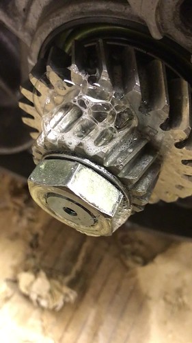 IMG_5825[1] IMG_5825[1] by Alan Kelly, on Flickr To be honest I was so surprised by the leak in this area, but after disassembling and resealing and testing the leak was resolved :-)But I still had some very small leaks around the intakes, but after an application of a smear of sealer to my new type intake gasket design (As it still was not perfect :-() At last I achieved a good leak test with a lose of only 0.7PSI over the 5 mins which I think should be OK. 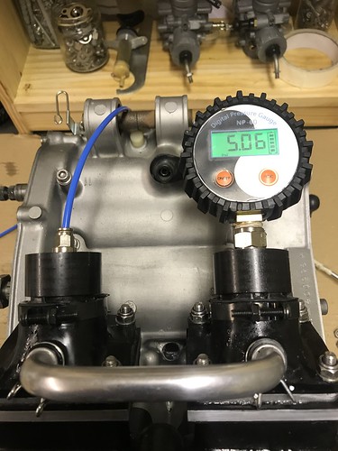 IMG_5826[1] IMG_5826[1] by Alan Kelly, on Flickr 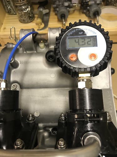 IMG_5827[1] IMG_5827[1] by Alan Kelly, on Flickr On the second test But to be honest, I was still not happy with the use of sealant to produce a air tight seal at the intakes, I decide to again look at the design and see if we could replace the the standard gasket type seal with a more robust O ring design, and after a few hours playing around with a 3d Cad model I managed to come up with a design that suited both the inlet port shape and the reed cage shape. Final Model of reed assembly 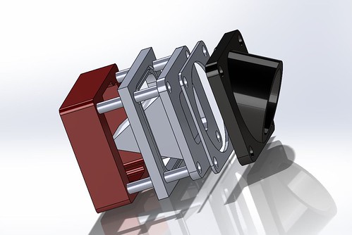 Reed assembly 1 Reed assembly 1 by Alan Kelly, on Flickr And the reed spacer / seal unit now has been designed two different O ring shapes to cope with both sides to create an effective O ring seal Barrel side 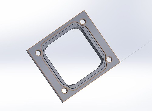 Barrel side Barrel side by Alan Kelly, on Flickr Reed side 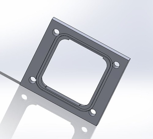 Reed side Reed side by Alan Kelly, on Flickr Once the design was complete, as we have on site a new 3D printer that can print using Carbon fiber to create carbon Fibre composites models, result!!! I have printed the design and fitted the design on the engine as shown below Reed assembly Kit 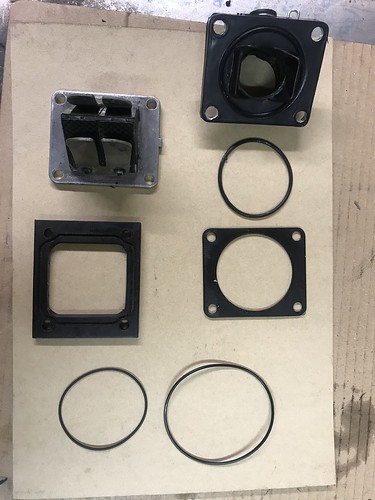 Reed seal kit Reed seal kit by Alan Kelly, on Flickr Reed spacer fitted with O rings 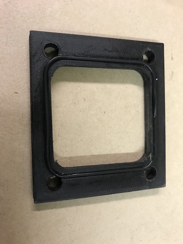 IMG_5842 IMG_5842 by Alan Kelly, on Flickr 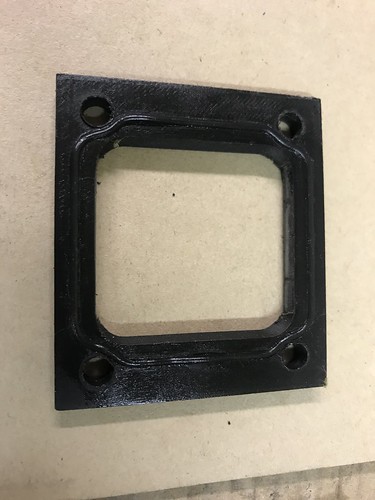 IMG_5844 IMG_5844 by Alan Kelly, on Flickr Spacer assembly on barrel 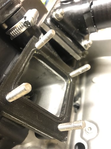 IMG_5845 IMG_5845 by Alan Kelly, on Flickr Reed fitted 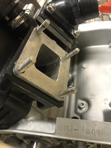 IMG_5846 IMG_5846 by Alan Kelly, on Flickr Reed to rubber inlet O ring support plate and additional O ring seal assembly fitted 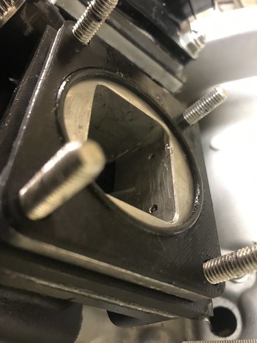 IMG_5848 IMG_5848 by Alan Kelly, on Flickr Inlet rubber fitted and tightened up with studs and normal nut arrangement 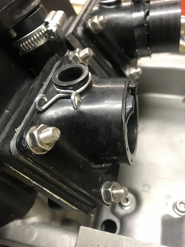 IMG_5851 IMG_5851 by Alan Kelly, on Flickr Additional Acorn nuts to act as both lock unts and to tart up Stud ends 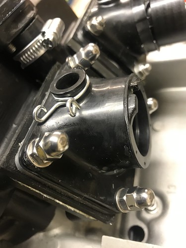 IMG_5852 IMG_5852 by Alan Kelly, on Flickr Retest leak test with new type sealing arrangement 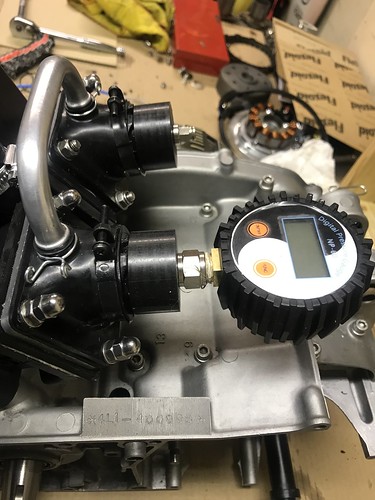 IMG_5853 IMG_5853 by Alan Kelly, on Flickr On retesting with the above design the leak test was a total success and had no leaks without the need to use any type of sealer :-) Plan now is to print off a second assembly, fit and test. And if all is OK I can start to look at finishing the engine build on the bench, and then look to getting engine back in the frame hopefully over Xmas. And hopefully long term (as the design is now tested) will try to get on the CNC and make at some point in the future some aluminium replacements. But for now the carbon Fiber composite should be fine That all for now folks but will catch up again soon, but if anybody want to know more please feel free to just ask as I am happy to share Best wishes Al. |
|
|
|
Post by marsbar350 on Dec 7, 2018 21:54:03 GMT 1
everytime I look at this thread you've come up with another great idea  fantastic alan  |
|
|
|
Post by mak595 on Dec 7, 2018 22:28:55 GMT 1
Very clever !
|
|
|
|
Post by bezzer on Dec 8, 2018 1:03:54 GMT 1
Excellent work Alan, really enjoying your updates and ingenious solutions!.
Keep up the good work Sir!
|
|
|
|
Post by dusty350 on Dec 8, 2018 20:41:41 GMT 1
Great skills as usual Alan Glad you got the leaks sorted. Do you think the studs are better than bolts now you have done the "O" rings ? Dusty |
|
|
|
Post by alankelly on Dec 8, 2018 20:56:48 GMT 1
Hi Dusty
Yes I will alway prefer studs if I can use this option as I have always been told that if you want a better more even clamp during the build of my Rover v8 it was recommended that both the head and crank bolts were changed from the factory bolts to ARP studs Kits made for the V8 And I think also this is why Yamaha used studs for the exhaust flange and the crank bearing case fasteners, the case is then clamped together more evenly in this critical area rather than use standard bolts, but I remain to be corrected👍
Also the studs have allowed me to tap out the full depth of the original hole and then I can screw the stud into the full depth to utlise the full thread depth to ensure I reduce to a minimum any chance of a stripped / pulled thread as my barrels are a little tired in this area and will then hope avoid any future repairs to the threads
Catch up again soon
Best wishes Al
|
|
|
|
Post by Tobyjugs on Dec 8, 2018 23:48:21 GMT 1
Hi Allen if all your threads are good you don't need to go much deeper than two times the depth of the diameter of the thread used and steel it's less. I cant remember the formula but it's not much more, I was taught that when using studs instead of bolts the torsional stress within the fasteners is less and should produce a more consistent clamping. Since then i have seen many arguments against what i have just quoted unless the studs are hydraulically tightened.
If the thread is damaged or tired i would do the same as you or repair the thread depending on options available. One thing i would advise against is drilling a deeper hole to make more thread, you could be drilling into a cooling water space or something just as critical.
|
|
|
|
Post by mikee on Dec 9, 2018 0:03:01 GMT 1
I love this stuff
I used 1mm gasket paper, and built press tools to cut them
Mike.
|
|
|
|
Post by alankelly on Dec 9, 2018 0:46:18 GMT 1
Hi Toby
No I just tapped the hole to its full depth as like you said, you could break into the water jacket of the barrel
And I used studs as like you mentioned my threads were not great and this fix is easier than helicoils
Best wishes Al
|
|
|
|
Post by alankelly on Dec 12, 2018 22:49:17 GMT 1
Hi all. Just a quick update on the yellow RD rebuild. Its getting colder in the shed now, but at last the engine is rebuilt and ready to be put back in its "home" Got the other carbon fiber composite reed spacer 3D printed the other day at work, and have now fitted and tested, and after a retest for leak down with both o ring type spacers, now losing less that 0.3 psi over the 5 mins proving the the Oring spacer really works OK without and need to use silicon sealant. and recon the leak is via my O ring seal on the exhaust flanges so pretty confident the engine is really air tight :-) 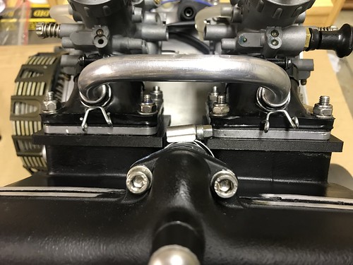 IMG_5891 IMG_5891 by Alan Kelly, on Flickr Also now fitted the Powerdynamo kit to replace the original burnt out system and pick up sensor has been correctly set up to 2mm BTDC as per Muttsnuts recommendation (Thanks Dave) 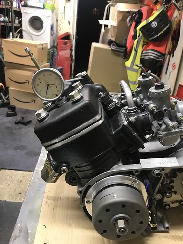 IMG_5876 IMG_5876 by Alan Kelly, on Flickr 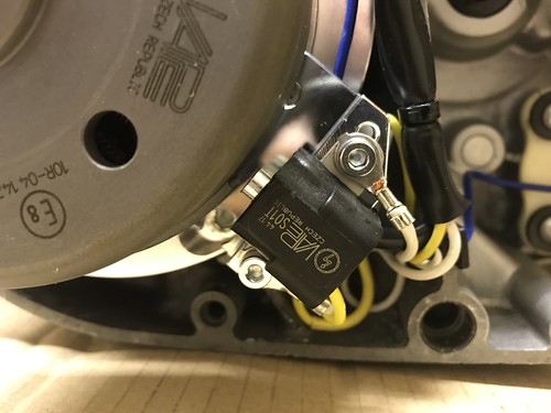 IMG_5877 IMG_5877 by Alan Kelly, on Flickr Lastly, as I am fitting a set of Higgspeed GP pipes that have "slip over / sliding joint" type engine to exhaust set up, to get a good seal, I decided to turn up a ring that fits both the original exhaust port diameter and the ID of the crushable exhaust sealing ring (so that the sealing ring is located / held central to the exhaust port bore) And then to prevent the exhaust flange from "twisting" in use (and so that it remains parallel to the barrel exhaust port flange to ensure the sealing ring as always clamped square) I have turned up a couple of S/S spacers so that the flange unit is bolted and tightened down onto a "fixed" face rather than just against the sealing ring to hopefully prevent the sliding joint flange from twisting or moving and then causing a leak. 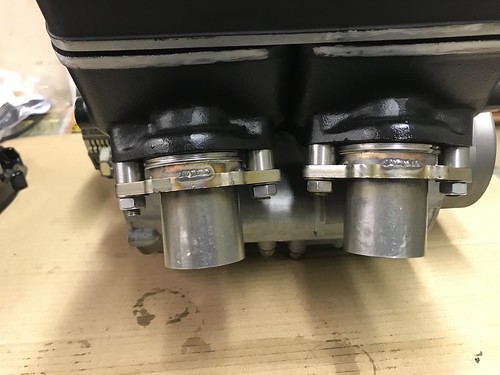 IMG_5887 IMG_5887 by Alan Kelly, on Flickr So with all this done engine is now ready and I will try to plan to get in "home" this weekend, as now need to start to make some space in the shed for the "new baby" that will be arriving hopefully in the next few days :-) 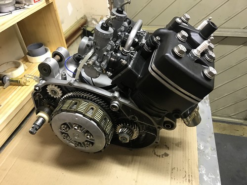 IMG_5884 IMG_5884 by Alan Kelly, on Flickr 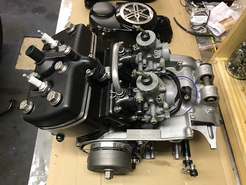 IMG_5882 IMG_5882 by Alan Kelly, on Flickr Catch up again soon. Best regards and happy Xmas to all Al. |
|
|
|
Post by alankelly on Jan 18, 2019 23:48:17 GMT 1
Hi all
Just finishing of the yellow project but have got sidetracked by the other build😁 at the moment but more picture of the finish build to follow soon👍
In my box of bits that I got with my donor engine I have a vacuum fuel tap and also the bike is fitted out with 31k carbs so my question is please if I fit this type of fuel tap is do I connect both carbs to the vacuum connection on the tap using a tee piece or just use one carb and blank off the other vacuum port on the other carb
Thanks in advance to all
Best wishes Al
|
|
|
|
Post by 4l04ever on Jan 19, 2019 0:40:20 GMT 1
Only one of the carbs has a fitting for the vacuum tap, so just a straight pipe from there to the tap connection.
|
|
|
|
Post by alankelly on Jan 19, 2019 1:06:54 GMT 1
Hi
Thanks for the info
Strange Do you know please which Carb choke or non choke should have this vacuum take off please? As on the carbs I have there is a stub connection on both that when I blew down exits out of a drilling / hole in the top of the mouth of the carb on the reed side. and both carbs have this drilling which I originally blanked off to prevent a vacuum leak hence my question. so I presume I blank one off and then just use the other
Many thanks for all your help
Best wishes Al
|
|
|
|
Post by alankelly on Jan 19, 2019 1:10:10 GMT 1
Ps here is a close up of the carbs with the two stubs in view pointing at each other  Thanks again Best wishes Al |
|
|
|
Post by jessy03 on Jan 19, 2019 8:55:04 GMT 1
They need linking - it’s the choke, the vacuum spigot is on the inside of the right carb, this connects to the fuel tap, there is only one.
Jess
|
|