|
|
Post by bezzer on Apr 11, 2022 19:33:04 GMT 1
I can only echo the previous comments Mark, I mean this as a compliment, when I say, you make it look easy mate. Stunning work.
|
|
|
|
Post by yamark on Apr 19, 2022 7:17:43 GMT 1
Cheers, Dusty, Denzil, Evochris, abar121, Yogi and Bezzer. Sorry chaps, for no updates this weekend- I was away in Kent for a wedding, which was spectacular. I'll be back on the build next weekend  Mark  |
|
|
|
Post by yamark on Apr 19, 2022 7:29:38 GMT 1
When you gonna stop these easy builds and make the FLYING YAMARK 😎😂  , Matt, I wish I had the imagination and anywhere near the ability of Mr Millyard. I'm also struggling (like most people) to get projects and parts at an affordable price  |
|
|
|
Post by yamark on Apr 24, 2022 20:29:38 GMT 1
More engine preparation. In mating two sets of crankcases together, you end up with a few non standard things to sort out. I have to form 2 trenches for the pegged crank bearings to locate into on the center bearings Marked out  SDC12151 SDC12151 I used a Dremel with an angled fine burr to produce the trenches  SDC12157 SDC12157 I then run a tap through all the threads after cleaning them with a cotton bud and some GT85  SDC12158 SDC12158 And then start to assemble the Tacho drive  SDC12159 SDC12159 I'm building the crankshaft at the moment, as I've decided my firing order. I also have the clutch to finish Cheers, Mark |
|
|
|
RD700LC
Apr 24, 2022 21:34:44 GMT 1
Post by donkeychomp on Apr 24, 2022 21:34:44 GMT 1
You did that with a Dremel? Fantastic Mark, you must have very steady hands!
Alex
|
|
|
|
Post by yamark on Apr 27, 2022 10:37:49 GMT 1
You did that with a Dremel? Fantastic Mark, you must have very steady hands! Alex Thanks Alex, I haven't got the hands of a surgeon . It's easy to do, you try not to think of the consequences if you slip. Slow and steady- don't get greedy runs through my head |
|
|
|
Post by yamark on May 1, 2022 21:49:08 GMT 1
Engine continued I assemble the selector mechanism, so I can fit the gearbox  SDC12160 SDC12160 One of the drawbacks of having an outrigger crankcase section is you have to split the cases to change anything on the left side of the standard engine. This includes, the pushrod oil seal, the gearbox output shaft seal, the gear change shaft oil seal, the outrigger bearing and the neutral switch! So I always fit new parts Neutral switch fitted, and screws fitted using Loctite Blue  SDC12161 SDC12161 New YPVS clutch arm bearing fitted  SDC12162 SDC12162 The gearbox fitted, and spacers machined to get the sealed outrigger bearing in place  SDC12163 SDC12163 Clutch fitted, so that I can work out pushrod length and how to fit a YPVS clutch adjuster into an LC input shaft  SDC12166 SDC12166 I've known for a while that I have to work this out. Note, this is just trial assembly, so that I can fabricate or modify any parts to make the gearbox/clutch work. Everything needs to be stripped and cleaned before assembly, so ignore the metal filings on the gearbox gears. I'm getting there - Cheers, Mark |
|
|
|
Post by dusty350 on May 1, 2022 21:53:38 GMT 1
It's getting closer now matey Awesome as always Dusty |
|
firebird67
L plate rider.
 2 strokes forever 😍😍😍
Posts: 31
|
Post by firebird67 on May 1, 2022 23:02:33 GMT 1
Looking fantastic, great attention to detail as always 👍
|
|
|
|
Post by bezzer on May 2, 2022 9:02:55 GMT 1
Looking good mate, outrigger bearing & spacer are looking superb.
|
|
|
|
Post by Tobyjugs on May 2, 2022 18:58:19 GMT 1
If fitted a stealth lockup clutch to a 4LO engine and had the same problem.
In the first instance I cut the adjuster down so that only the thread from the adjuster was entering the shaft. I ran it for a long time like this even though it was supposed to be a temporary fix
Later i used a special drill used for drilling very hard steel. I can't remember the name now they also use them for drilling armour plating.
If I remember correctly you have to go from 8mm to 12mm on the end of the output shaft. It does get a bit thin
I put the shaft in a lathe and just drilled it deep enough to fit the adjuster and YPVS ball into the end of the shaft.
|
|
|
|
RD700LC
May 2, 2022 19:00:50 GMT 1
via mobile
Post by Tobyjugs on May 2, 2022 19:00:50 GMT 1
Mark are you going standard clutch format?
|
|
|
|
Post by yamark on May 2, 2022 20:41:52 GMT 1
If fitted a stealth lockup clutch to a 4LO engine and had the same problem. In the first instance I cut the adjuster down so that only the thread from the adjuster was entering the shaft. I ran it for a long time like this even though it was supposed to be a temporary fix Later i used a special drill used for drilling very hard steel. I can't remember the name now they also use them for drilling armour plating. If I remember correctly you have to go from 8mm to 12mm on the end of the output shaft. It does get a bit thin I put the shaft in a lathe and just drilled it deep enough to fit the adjuster and YPVS ball into the end of the shaft. Hi Tobyjugs, I used small grinding stones to open out the internal bore. I used my pillar drill at first, then moved on to the lathe. It took a while though  . I think the adjuster is about 40mm long, so I cut it down by 5mm to save a bit of time. So I managed to bore down to a depth of 35mm- the shaft is very hard(no laughing at the back  ). I kept the center post the same length, so the ball bearing stays in the 8mm part of the shaft. It works well. I'm using one of Muttsnuts competition lockup clutches. It's a ball bearing type, quite compact and means I can keep a standard looking clutch cover. I should be posting up the details in the next week or two. Thanks mate for the information  |
|
|
|
Post by Denzil on May 3, 2022 7:30:51 GMT 1
Superb Engineering as always. Thanks for sharing this with the group. It's very exciting watching the machine come alive.
|
|
|
|
Post by Tobyjugs on May 3, 2022 22:41:52 GMT 1
If fitted a stealth lockup clutch to a 4LO engine and had the same problem. In the first instance I cut the adjuster down so that only the thread from the adjuster was entering the shaft. I ran it for a long time like this even though it was supposed to be a temporary fix Later i used a special drill used for drilling very hard steel. I can't remember the name now they also use them for drilling armour plating. If I remember correctly you have to go from 8mm to 12mm on the end of the output shaft. It does get a bit thin I put the shaft in a lathe and just drilled it deep enough to fit the adjuster and YPVS ball into the end of the shaft. Hi Tobyjugs, I used small grinding stones to open out the internal bore. I used my pillar drill at first, then moved on to the lathe. It took a while though . I think the adjuster is about 40mm long, so I cut it down by 5mm to save a bit of time. So I managed to bore down to a depth of 35mm- the shaft is very hard(no sblack personing at the back ). I kept the center post the same length, so the ball bearing stays in the 8mm part of the shaft. It works well. I'm using one of Muttsnuts competition lockup clutches. It's a ball bearing type, quite compact and means I can keep a standard looking clutch cover. I should be posting up the details in the next week or two. Thanks mate for the information Crikey that must of took a long time or a lot of stone's to take that much out. I did think about finishing my shaft off with a grinding stone. I decided the rough finish would let oil pass more easily to the ball bearing. This is of course all down to experience and personal feeling with these things. |
|
|
|
Post by yamark on May 8, 2022 17:57:46 GMT 1
Hi Tobyjugs, I used small grinding stones to open out the internal bore. I used my pillar drill at first, then moved on to the lathe. It took a while though . I think the adjuster is about 40mm long, so I cut it down by 5mm to save a bit of time. So I managed to bore down to a depth of 35mm- the shaft is very hard(no sblack personing at the back ). I kept the center post the same length, so the ball bearing stays in the 8mm part of the shaft. It works well. I'm using one of Muttsnuts competition lockup clutches. It's a ball bearing type, quite compact and means I can keep a standard looking clutch cover. I should be posting up the details in the next week or two. Thanks mate for the information Crikey that must of took a long time or a lot of stone's to take that much out. I did think about finishing my shaft off with a grinding stone. I decided the rough finish would let oil pass more easily to the ball bearing. This is of course all down to experience and personal feeling with these things. My theory is that when a diameter has to be reduced on a hardened shaft, it seems to be ground. Silver steel is also ground to size. I've drilled hardened steel before and it's hard as nails, so I ground the internal diameter instead of drilling. Great questions mate |
|
|
|
Post by yamark on May 8, 2022 18:41:10 GMT 1
Cheers Dusty, Firebird67,Bezzer, Tobyjugs and Denzil. Clutch continued I did take a picture of the ground out clutch shaft, ignore the used lock tab.  SDC12165 SDC12165 To assemble the clutch, I needed a hub nut. This is NLA from Yamaha - Dusty to the rescue, he very kindly sent me one- top man mate The lock up clutch assembled, so I can sort out the pushrod  SDC12167 SDC12167 New pushrod installed, and clutch YPVS arm  SDC12168 SDC12168  SDC12169 SDC12169 I can now machine the pushrod to length 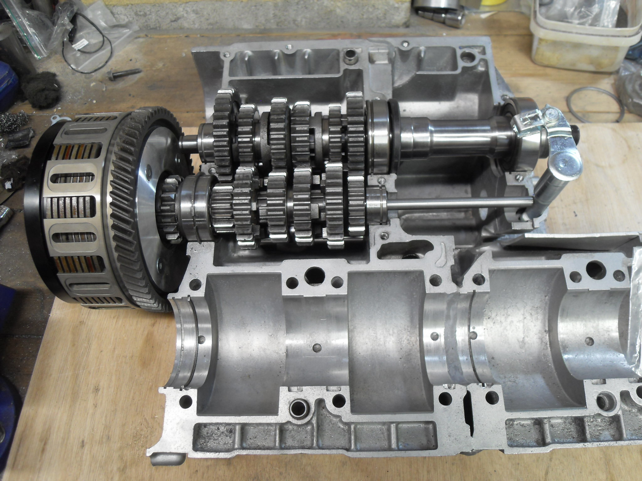 SDC12170 SDC12170 r Just the crank to build and it can be bolted together. Cheers, Mark |
|
|
|
Post by Tobyjugs on May 8, 2022 19:44:59 GMT 1
Hi Mark just a heads up. The ball bearings that were suplied with my stealth lockup clutch were 8mm + - 0.03mm.
I found they were a bit sticky in the grooves of the plate. I put all the smallest balls in.
When I opened it up quite a few were jammed in the grooves (40%).
It never seemed to affect the performance of the clutch and wasn't noticed in use.
I ended up changing the balls for 5/16 diameter balls or 7.93mm.
Still no difference in clutch operation but upon inspection the balls still moved freely within the grooves.
|
|
|
|
Post by midlifecrisisrd on May 8, 2022 20:01:06 GMT 1
Absolutely fecking awesome Mark
Steve
|
|
|
|
Post by yamark on May 8, 2022 20:29:19 GMT 1
Hi Mark just a heads up. The ball bearings that were suplied with my stealth lockup clutch were 8mm + - 0.03mm. I found they were a bit sticky in the grooves of the plate. I put all the smallest balls in. When I opened it up quite a few were jammed in the grooves (40%). It never seemed to affect the performance of the clutch and wasn't noticed in use. I ended up changing the balls for 5/16 diameter balls or 7.93mm. Still no difference in clutch operation but upon inspection the balls still moved freely within the grooves. Thank mate for the heads up, any information is helpful, I'll change the ball bearings. I've learnt over the years that tried and tested is way better than theory. I'll let you know how I get on |
|
|
|
Post by yamark on May 8, 2022 20:30:38 GMT 1
Absolutely fecking awesome Mark Steve Thanks Steve, amazing comment from an LC God ATB, Mark |
|
|
|
Post by rich on May 8, 2022 20:39:37 GMT 1
Great stuff Mark and thank you for keeping us updated |
|
|
|
Post by dusty350 on May 8, 2022 20:43:04 GMT 1
Looking really awesome now Mark Not far off now Dusty |
|
|
|
Post by sidney81 on May 8, 2022 21:28:52 GMT 1
Awesome mark ,this is exciting!!
|
|
|
|
Post by donkeychomp on May 8, 2022 21:35:04 GMT 1
I've just bought shares in Butterkist so I can keep up with this. Bonkersly good work Mark!
Alex
|
|
|
|
Post by oldbritguy on May 9, 2022 9:28:56 GMT 1
Hi Mark
I never fully appreciated the additional challenges (not that you haven’t had a few already 😂) with engineering the inboard gearbox. The potential for hidden oil leaks from clutch pushrod, gearbox output shaft (original has collar retained by sprocket and nut), and selector shaft seal. All hidden inside!!
Plus an extra sprocket bearing, half ring and seal at the end of the extended shaft just to keep things running smoothly.
I am also impressed with the clutch operating set up. Does the original lc pushrod seal fit your new pushrod?
I would also over engineer an extra bearing at the mechanism end just to support the pushrod, though that then asks another question about keeping the bearing lubed at engine speeds. I know the pushrod doesn’t turn much so maybe just a simple bush?
You never said it would be easy bud. Hats off
John.
|
|
|
|
RD700LC
May 10, 2022 16:38:48 GMT 1
Post by yamark on May 10, 2022 16:38:48 GMT 1
Cheers, Tobyjugs, Midlifecrisisrd, Rich, Dusty, Sidney81, and Donkeychomp Comments, without doubt spur me on, so thanks chaps |
|
|
|
Post by yamark on May 10, 2022 17:16:54 GMT 1
Hi Mark I never fully appreciated the additional challenges (not that you haven’t had a few already 😂) with engineering the inboard gearbox. The potential for hidden oil leaks from clutch pushrod, gearbox output shaft (original has collar retained by sprocket and nut), and selector shaft seal. All hidden inside!! Plus an extra sprocket bearing, half ring and seal at the end of the extended shaft just to keep things running smoothly. I am also impressed with the clutch operating set up. Does the original lc pushrod seal fit your new pushrod? I would also over engineer an extra bearing at the mechanism end just to support the pushrod, though that then asks another question about keeping the bearing lubed at engine speeds. I know the pushrod doesn’t turn much so maybe just a simple bush? You never said it would be easy bud. Hats off John. Hi John, such a well thought out question. There were drawbacks with using the LC clutch actuator set up. You loose 4 clutch cover fixing points, as the generator cover is no longer in line with the main section of the cover. I had to fabricate extra fixings on the triple to get over this. The clutch cable would also be "seen,"and hard to route between the carbs and under the fuel tank. I opted for a YPVS set up for this reason. You are right, the half ring locates the gearbox bearing, and I've had to install spacers between that bearing and the outrigger bearing, and another spacer between the outrigger bearing and rear of the sprocket! The original pushrod is an imperial size, and made of silver steel. I've used the same diameter and material.(the original seal therefor fits) If you try to bend the rod, it flexes very little and springs back straight. I checked the difference in deflection between the standard YPVS rod and the new longer rod. It deflects 0.6mm more at the end without the seal fitted. I feel, if I install a bearing or bush, it will possibly wear the pushrod. If I beef up the rod between the seal and the clutch arm, I would have to split the cases to change the rod. With this set up, I can change the pushrod from the clutch side, I can maintain and grease the clutch arm as well. The only thing I can't do is change the pushrod seal without splitting the cases. Great question John, thanks for your interest. Cheers, Mark |
|
|
|
Post by stirling11 on May 11, 2022 15:18:55 GMT 1
Hi Mark
Superb works as usual
A question about the gear box outrider shaft, is it a solid shaft or hollow
And I hope I've got this correct
The solids give less moment of inertia that you have to contend with, the hollow machined out shaft has more moment of inertia and will allow for more torque, it's also more stiffer an stronger than the same weight of a solid one.
They hollow shafts won't develop more power transmitted, however their power to weight ratio is better than a solid, solids don't bend as much as hollow
Each has it's own advantages and disadvantages, I suspect it won't have much of an effect in your application, however I hope it's useful info in case the right bearing on the shaft flogs out
|
|
|
|
RD700LC
May 15, 2022 19:36:09 GMT 1
Post by yamark on May 15, 2022 19:36:09 GMT 1
Hi Mark Superb works as usual A question about the gear box outrider shaft, is it a solid shaft or hollow And I hope I've got this correct The solids give less moment of inertia that you have to contend with, the hollow machined out shaft has more moment of inertia and will allow for more torque, it's also more stiffer an stronger than the same weight of a solid one. They hollow shafts won't develop more power transmitted, however their power to weight ratio is better than a solid, solids don't bend as much as hollow Each has it's own advantages and disadvantages, I suspect it won't have much of an effect in your application, however I hope it's useful info in case the right bearing on the shaft flogs out Brilliant info, I didn't know any of that . The output shaft is solid, the same as the standard shaft, but longer. I think I'm correct in saying Yamaha always use solid gearbox output shafts. |
|


 , Matt, I wish I had the imagination and anywhere near the ability of Mr Millyard.


 .
. ).
).


