|
|
Post by oldbritguy on Apr 13, 2020 9:15:49 GMT 1
Nice work Mark and a really clever piece of engineering requiring a considerable bit of thought. With a 90 degree cross plane crank you will have 2 pairs of pistons each 180 apart and so will still have your "wasted" spark with one of each pair at BDC. 2 pick ups at 90 degrees on the stator back plate will work with the standard rotor magnets and use 2 x twin output ignition coils wired separately for each pick up. This will give you your firing at every 90 degrees with a wasted spark on the opposite piston from TDC. (same as 4 stroke 4s but compensated for 2T with 90 degree mount) You will need to ensure your additional pick up is on a movable adjustable mount for final dialing in (independent of the original) once up and running. Hope this makes sense as it has got my head spinning too lol  Loving the progress mate..total respect John |
|
|
|
Post by yamark on Apr 13, 2020 9:25:52 GMT 1
Thanks Mark for the answer re oil line checkvalves, after I sent you that message midweek I came across a classic forum racing link that said ellis had injured himself, and he was not doing any work for the time. I was going to post again about ellis, but muttsnuts clears it up . I too hope he is on the mend as I didnt realize how bad he was. Who is making your gearbox shaft now? and did you choose another engineering company because ellis couldnt help with the longer version needed this time..... thanks Allen Millyard sent me the link for those check valves, but with vital components, I like to be sure it's the best choice. I have more valves on the way- I'll test them all, but my reserve plan is to fit check valves from a Suzuki. 500RG kindly told me the details of them, but they would work out at £92 for 4 if bought them in the UK.
One of my mates (who races sidecars), told me about Ellis. I don't know the details, but from what I was told, it sadly will be life changing for Ellis. I'm fairly sure he will not be returning to work in the foreseeable future, or if ever, but I'm hearing this second hand! He's a true gent and I wish him the best outcome.
When I had the triple shaft made, I had 3 quotes. Ellis- cheapest, a local engineers- a bit more expensive, and Nova Racing- off the Richter Scale expensive. I went with Ellis because of his vast experience and I simply liked him, no bullshit or false promises, he warned me he was busy. He said it would be 3 or 4 months, and he completed the shaft in just over 3 months. He was a delight to deal with.
I've just got to get to my local engineers, when the government allows me out to play 
|
|
|
|
Post by yamark on Apr 13, 2020 9:54:33 GMT 1
Nice work Mark and a really clever piece of engineering requiring a considerable bit of thought. With a 90 degree cross plane crank you will have 2 pairs of pistons each 180 apart and so will still have your "wasted" spark with one of each pair at BDC. 2 pick ups at 90 degrees on the stator back plate will work with the standard rotor magnets and use 2 x twin output ignition coils wired separately for each pick up. This will give you your firing at every 90 degrees with a wasted spark on the opposite piston from TDC. (same as 4 stroke 4s but compensated for 2T with 90 degree mount) You will need to ensure your additional pick up is on a movable adjustable mount for final dialing in (independent of the original) once up and running. Hope this makes sense as it has got my head spinning too lol Loving the progress mate..total respect John Hi John, thanks for confirming my thoughts. The Ignitech accepts 2 input signals from the pick ups. It's battery CDI, so no charge coils needed like the standard LC, so a YPVS generator is used.
I'll explain it to the chaps in my next post, but yes, the flywheel has 2 magnets, so with 2 pick ups at 90 degrees, I'll get a signal every 90 degrees. The signal, will pulse from the pick up at 5 o'clock, then 2 o'clock by the first magnet, then repeated on the second magnet on the flywheel. The Ignitech will then send the voltage to the coils. As it has 2 programmable outputs, this pulse will be alternating between the outputs. So as you say, still a wasted spark, so I'll get 8 sparks per revolution of the crankshaft!
This is where the maths gets interesting. If the engine revs to 10,000 RPM (I'll be under that) - that's 166 revs per second I'll have 1328 sparks per second!!, but only 664 per second burning fuel. 
Mind blowing, Mark 
|
|
|
|
Post by yamark on Apr 13, 2020 9:57:56 GMT 1
I keep on forgetting just how much stuff needs doubling up on this build. Coils, pipes, carbs...keep it up Mark! Alex Thanks Alex, yes it's hard to fit it all in on a bike designed for 350cc! But no one's forcing me to do this
|
|
rddave
L plate rider.

Posts: 16 
|
Post by rddave on Apr 14, 2020 15:45:48 GMT 1
Nice work Mark and a really clever piece of engineering requiring a considerable bit of thought. With a 90 degree cross plane crank you will have 2 pairs of pistons each 180 apart and so will still have your "wasted" spark with one of each pair at BDC. 2 pick ups at 90 degrees on the stator back plate will work with the standard rotor magnets and use 2 x twin output ignition coils wired separately for each pick up. This will give you your firing at every 90 degrees with a wasted spark on the opposite piston from TDC. (same as 4 stroke 4s but compensated for 2T with 90 degree mount) You will need to ensure your additional pick up is on a movable adjustable mount for final dialing in (independent of the original) once up and running. Hope this makes sense as it has got my head spinning too lol Loving the progress mate..total respect John Hi John, thanks for confirming my thoughts. The Ignitech accepts 2 input signals from the pick ups. It's battery CDI, so no charge coils needed like the standard LC, so a YPVS generator is used.
I'll explain it to the chaps in my next post, but yes, the flywheel has 2 magnets, so with 2 pick ups at 90 degrees, I'll get a signal every 90 degrees. The signal, will pulse from the pick up at 5 o'clock, then 2 o'clock by the first magnet, then repeated on the second magnet on the flywheel. The Ignitech will then send the voltage to the coils. As it has 2 programmable outputs, this pulse will be alternating between the outputs. So as you say, still a wasted spark, so I'll get 8 sparks per revolution of the crankshaft!
This is where the maths gets interesting. If the engine revs to 10,000 RPM (I'll be under that) - that's 166 revs per second I'll have 1328 sparks per second!!, but only 664 per second burning fuel.
Mind blowing, Mark
Scratching my head with this, electrickery is the devils work Cracking build
|
|
|
|
Post by raven13 on Apr 15, 2020 1:05:02 GMT 1
lost me on page 1 and again on every page since but loving the build
|
|
|
|
Post by yamark on Apr 19, 2020 21:16:16 GMT 1
Ignition continued
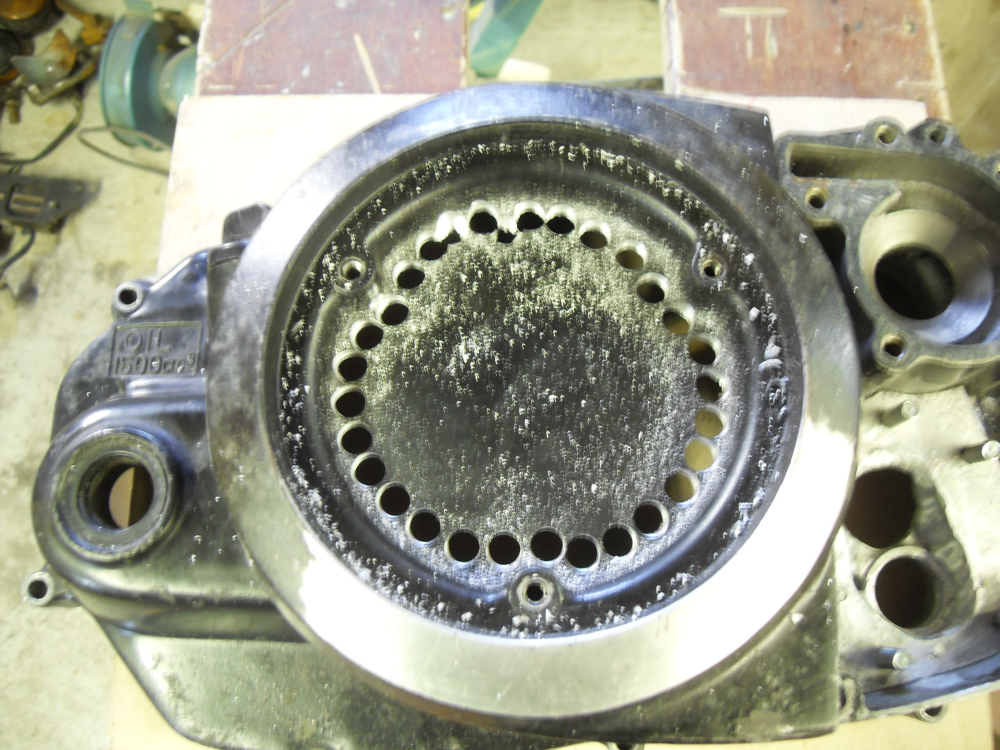
Last week, I started to dismantle the Power Dynamo to fit the second pick up coil. Now, the problem is the bike and crankcases are with Mick Abbey, so I can't photograph what I have to describe, but here goes.
With the Power Dynamo (PD), the stator plate is fixed by the three screws (like standard), with the pick up at about 4 o'clock. I need 90 degrees between the standard position pick up and the second pick up which will be at about 1 o'clock. The problem is, at 1 o'clock the LC has a casting to fit the generator cover. So both pick ups must move approximately 15mm clockwise. The PD doesn't use a woodruff key to locate the flywheel, so the flywheel can be rotated so the trigger magnets move to the new position.
This means I have to the drill and tap new holes for both pick ups. As luck would have it, the steel ring that the pick up bracket is fixed to, has a hole 16mm clockwise from it original position- so now I only need to drill and tap 3 holes.
The new hole drilled - it's the one with the black arrow
 SDC11767 SDC11767
I then tap the new hole (3mm thread), so the drill size was 2.5mm
 SDC11768 SDC11768
Now I need the second pick up holes 90 degrees anti clockwise, so I mark the right hand hole of the new fixing bracket
 SDC11769 SDC11769
Again, drill/tap and fix the right hand side of the new bracket (I'll counter sink later), so I can accurately mark the left hole.
 SDC11771 SDC11771
And finally, drill and tap the left hole and reassemble the generator
 SDC11774 SDC11774
The generator cover will need to be altered to accommodate the new pick up. As Muttsnuts pre programmed the Ignitech, that's most of the ignition and generator finished.
Sorry if I've given anyone "brain ache"
Cheers, Mark
|
|
|
|
Post by Yogi on Apr 19, 2020 21:26:40 GMT 1
Keep em coming Mark
My brains 🧠 not aching it’s left the building 🤯
Matt 🧸
|
|
|
|
Post by donkeychomp on Apr 19, 2020 21:55:54 GMT 1
My cerebellum has just fused but keep it up Mark!
Alex
|
|
|
|
Post by oldbritguy on Apr 19, 2020 21:58:45 GMT 1
That is smart Mark. Nice tidy job too.
Will you need to put some means of adjustment into the pick up mounts or are you happy that once bolted up it will be spot on. i.e. fine tuning will be achieved with the rotor position on the crank taper.
Really looking forward to your next updates, your problem solving skills are superb.
John
|
|
|
|
RD700LC
Apr 21, 2020 18:58:50 GMT 1
Post by yamark on Apr 21, 2020 18:58:50 GMT 1
That is smart Mark. Nice tidy job too. Will you need to put some means of adjustment into the pick up mounts or are you happy that once bolted up it will be spot on. i.e. fine tuning will be achieved with the rotor position on the crank taper. Really looking forward to your next updates, your problem solving skills are superb. John Hi John, the pick up brackets are as close to 90 degrees that I could get them. I would say there is some fine adjustment in the pick up's, as the holes in the base of the pick ups, has a bit of clearance in all directions.
I do find it a bit odd that the new flywheel is not keyed to the crank. It's just a taper fit. I think the makers might have done this so it will fit several models. So the position of the flywheel is fairly crucial when it's bolted tight.
And thank you for your kind words and encouragement
|
|
|
|
Post by jon on Apr 21, 2020 19:58:00 GMT 1
I remember having fitted a 50cc electric start flywheel to a 210cc Vespa once.
The electric start ring was removed to reduce weight and a second woodruff key slot had been machined for the different model.
It would worry me too if it had no slot and will definitely put me off buying one.
That said if it didn’t work they wouldn’t sell them, so I’m confident it will be fine.
Just make sure you use fine grinding paste to lap the flywheel to the crank taper for maximum grip.
Jon
|
|
|
|
Post by 4l04ever on Apr 21, 2020 23:06:05 GMT 1
There should also be adjustment in the Ignitech for the angle between the two banks.
While I was messing with my ignition system on my 3XV, we removed the woodruff key and rotated the flywheel to get more advance. It never moved with no woodruff key so if on tight enough you should be good.
|
|
|
|
Post by Eyrey1 on Apr 21, 2020 23:15:54 GMT 1
didnt know you were building another one mark ! lol
|
|
fieroman
L plate rider.
Live to ride, ride to live
Posts: 22
|
Post by fieroman on Apr 23, 2020 21:55:38 GMT 1
nice work mark. i have a quick quizz for you. what angle did you mount the side stand bracket. i have an 82 im working on which it was removed. thanks so much. mark from canada
|
|
|
|
RD700LC
Apr 24, 2020 14:17:22 GMT 1
Post by yamark on Apr 24, 2020 14:17:22 GMT 1
nice work mark. i have a quick quizz for you. what angle did you mount the side stand bracket. i have an 82 im working on which it was removed. thanks so much. mark from canada Hi Mark from Canada. I've measured my standard 350LC, and while not exact, I measure the angle from vertical for the side stand as 30 degrees. I also measured the side stand distance to the ground. The bike was upright, standard tyres, tyre pressures. Stand fully down against the stop. I measure from the lowest point of the side stand to the ground as 50mm
Hope that helps, good luck with the bike
Cheers, Mark
|
|
|
|
Post by muttsnuts on Apr 25, 2020 18:30:42 GMT 1
in the ignitech we can fine tune the actual "offset" for the spark angle/pickup for each pickup, so even if its out by a couple of degrees, we can adjust it accordingly to find the best setting, but since this isn't a race bike, so long as its all running smoothly, I doubt Mark will be looking to squeeze every last ounce out of the engine !
|
|
|
|
RD700LC
Apr 26, 2020 18:58:20 GMT 1
Post by yamark on Apr 26, 2020 18:58:20 GMT 1
in the ignitech we can fine tune the actual "offset" for the spark angle/pickup for each pickup, so even if its out by a couple of degrees, we can adjust it accordingly to find the best setting, but since this isn't a race bike, so long as its all running smoothly, I doubt Mark will be looking to squeeze every last ounce out of the engine ! Dave, your so right about it not being a race bike , there's a lot more metal whizzing around at speed, so I told Mick Abbey to tune the cylinders/make the exhausts so the engine makes it's peak power lower than standard, maybe 1,000 rpm lower for everything.
Cleaver things, Ignitechs
|
|
|
|
Post by yamark on Apr 26, 2020 19:37:16 GMT 1
The clutch on the 700 will be standard primary drive, billet basket, FZ600 frictions, powervalve type actuation and ball bearing lock up. The lock up clutch was supplied by Muttsnuts (thanks Dave), and with a bit of modification to the LC clutch cover will fit. You can just grind back the 3 lugs for clearance. I decided to do the same as the triple and cut out the 3 lugs that are for the screws to hold the plastic cover disc on.
So first, I drill a series of holes using my pillar drill
 SDC11775 SDC11775
The centre section removed
 SDC11776 SDC11776
The left cover that is about to meet it's maker. This cover has a lug snapped off, and I need the raised section at the generator pick up, to modify the generator cover to accept 2 pick ups.
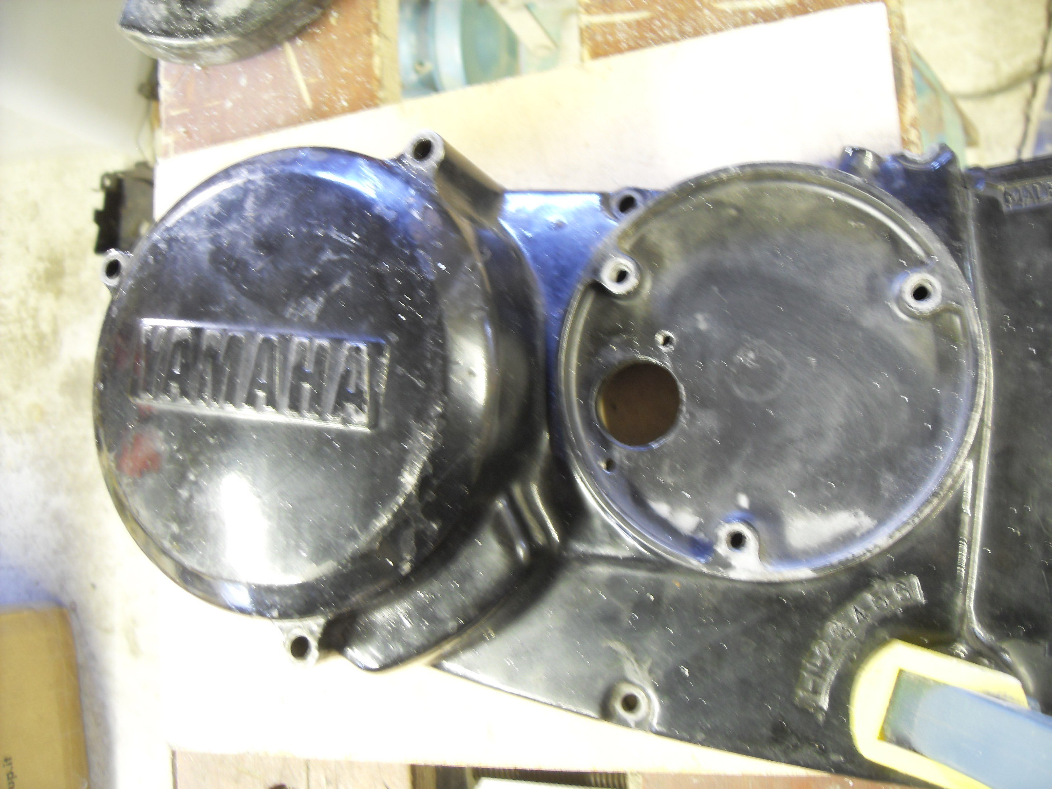 SDC11777 SDC11777
Disc removed
 SDC11778 SDC11778
I grind the disc to a circle and grind the cover so just a small step is left, for the disc to be welded to.
 SDC11779 SDC11779
I then made a gear change shaft protection tube. The tube was drilled using a chuck in the tailstock of the lathe
 SDC11780 SDC11780
And the finished article
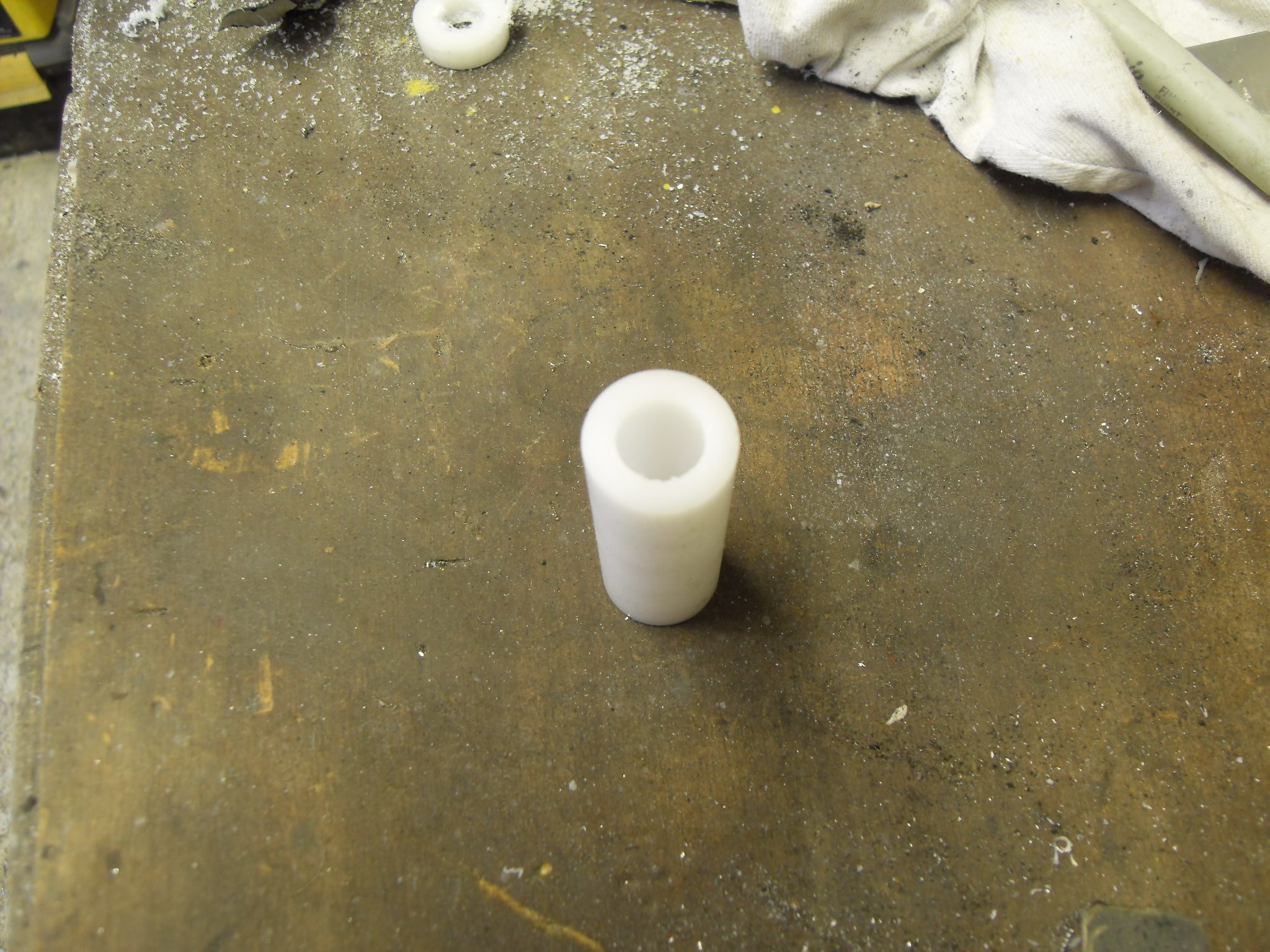 SDC11784 SDC11784
Lastly, I worked out the routing of the oil lines for the pump. I had to rotate the inlet pipe elbow, and 2 outlets to allow the oil pump cover to have as little modification as possible, it's a squeeze but I've got the oil pump cover figured out
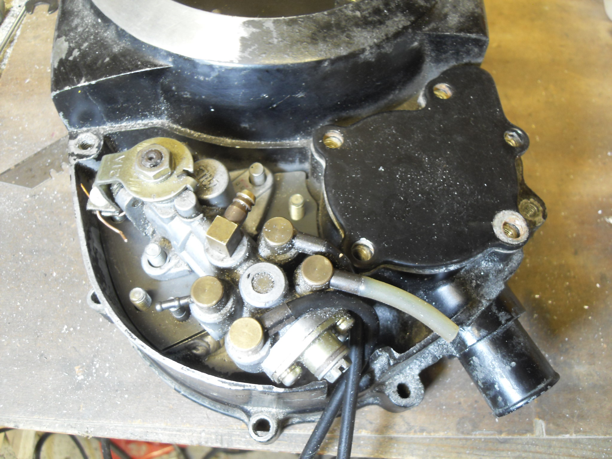 SDC11772 SDC11772
Dare I say, it's going well
Cheers, Mark
|
|
|
|
Post by donkeychomp on Apr 26, 2020 21:48:26 GMT 1
Engineering witchcraft. I love it!
Alex
|
|
|
|
Post by dusty350 on Apr 26, 2020 21:55:08 GMT 1
Great work, as always mate Dusty |
|
|
|
Post by jediwhite on Apr 26, 2020 22:43:44 GMT 1
I'm so glad I joined this forum, Engineering excellence and all explained perfectly, cheers
|
|
|
|
Post by rich on Apr 26, 2020 23:27:13 GMT 1
Just popped back to this thread for a catch up. Your problem solving and attention to detail never ceases to amaze me Mark! Looking forward to reading the next update Cheers, Rich |
|
|
|
Post by Denzil on Apr 27, 2020 8:29:24 GMT 1
Just fantastic. Engineering at its best. Men in sheds building stuff. Top work Mark.
|
|
|
|
Post by yamark on May 3, 2020 19:52:40 GMT 1
Cheers lads .
I wanted to keep the oil pump cover, looking as standard as possible. Once I realised the RG500 pump can't fit under the standard cover, I set about modifying. Dusty supplied me with a YPVS cover, so after much measuring, I cut up both covers. I kept removing material from the LC cover, until the pump cleared. Then worked out the section of the YPVS cover needed to enclose everything. The oil lines will exit like the standard LC, with a modified bung. The middle fixing can't be used as it's been removed from the clutch cover,as it was in the way of the pump.
I didn't take any pictures of the cutting and plastic welding, but I then filled, rubbed down and used some spray stopper. For those that don't know, stopper is like a very fine filler. It's yellow in the photo, I then rubbed down again
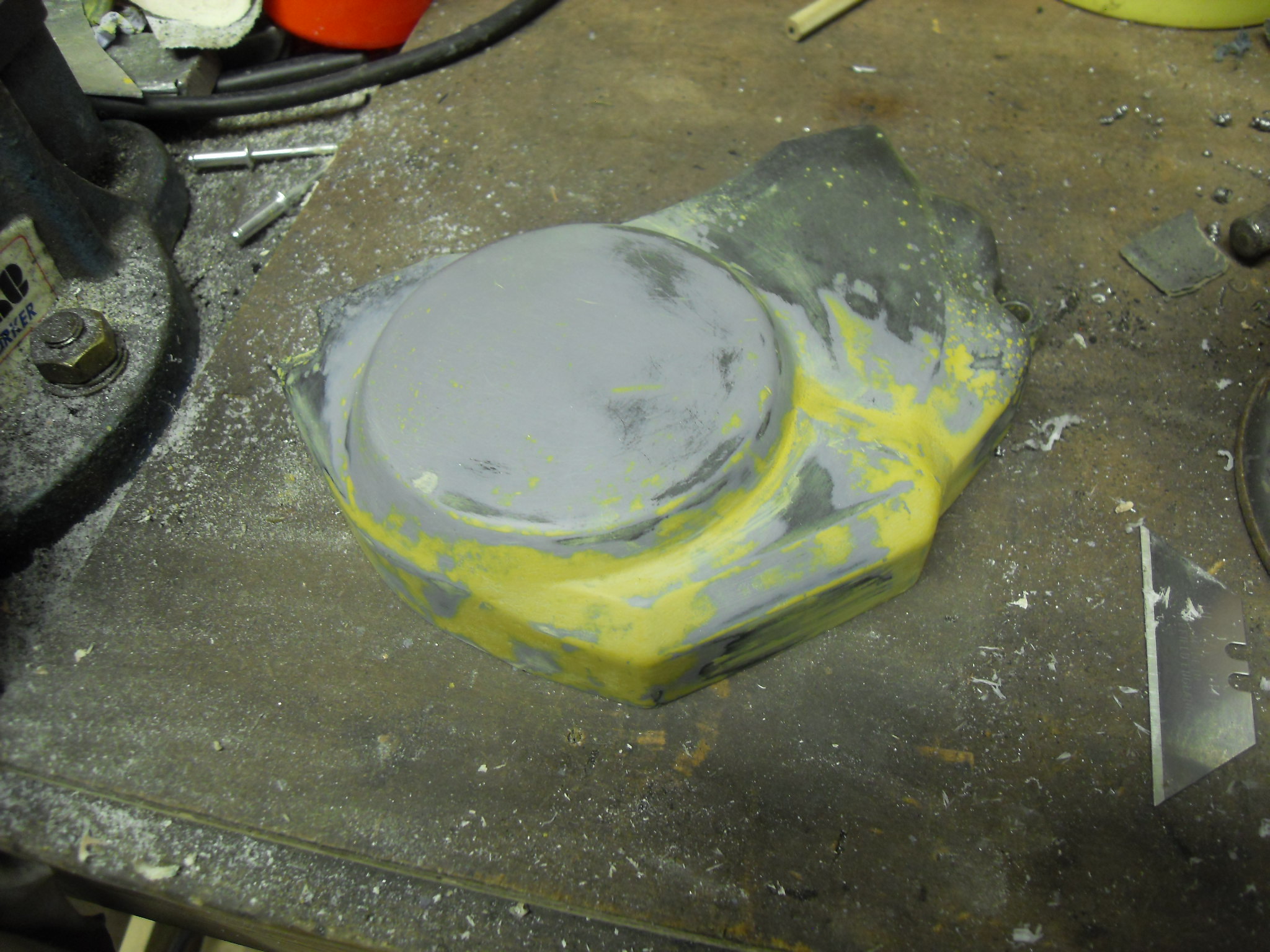 SDC11781 SDC11781
I then painted the primer
 SDC11783 SDC11783
 SDC11782 SDC11782
The cover isn't finished yet, it still has a few imperfections that I'll sort out later.
Cheers for all your comments, Mark
|
|
|
|
Post by Tobyjugs on May 4, 2020 8:32:27 GMT 1
Nice job on the cover Mark  |
|
|
|
Post by oldbritguy on May 4, 2020 13:30:58 GMT 1
Great work Mark
Nice n steady 😎
John
|
|
|
|
Post by bezzer on May 4, 2020 21:56:11 GMT 1
Stunning attention to detail Mark, fabrication of the oil pump cover is superb.
|
|
|
|
Post by marrcel on May 5, 2020 17:50:08 GMT 1
One question on the cdi. Do you use wasted spark?
|
|
|
|
Post by yamark on May 6, 2020 13:53:22 GMT 1
One question on the cdi. Do you use wasted spark? Hi Marrcel, the short answer is yes. The easiest way to think of my ignition system is the same as a standard LC using an Ingnitech and banshee type coils. Then adding another complete ignition system, triggered 90 degrees after the original. The Ignitech has 2 channels, so I don't need 2 CDI boxes.
Hope that makes it a bit clearer.
Thanks for the question Marrcel,
Cheers, Mark
|
|


