|
|
Post by joossio on Aug 2, 2022 16:28:25 GMT 1
Hello Folks, My name is Joost, im 27 and im from Holland. A while back i've started a new project. I helped out a friend picking up a Aprilia RS250 frame+swing arm because he was sick. Delaying the deal wasnt an option due to the rarety of those stuff in Holland. But when i had it laying at home he said, "if you want you can use it for your own, i would've putted into storage for later" First of all i was like, "nah im alright, got plenty stuff". But eventually the idea kept growing and i went for it. An Aprilia RS250 frame where i will put a RD350 YPVS engine in. Aprilia looks with propper Yamaha power. This is what i picked up. A bare frame with a swingarm. Soon after that i went on a search for parts. - Front fork - Front wheel - Rear wheel - Engine - Etc The idea was to go for a Aprilia front fork + wheel. But due to the prices i went for a R1 front fork because the discs have the same spacing between each other. And it will be a Hybrid so a little mix isn't that bad. I've made a new steering stem myself and pressed it into the yoke. Also i made a jig to keep everything nice and level.  Then i started with getting the engine in rougly in the right place.  Now i had it rougly in the right place, the fun stuff came. 

 Finally the engine was in it's correct position. The first idea was to make the H-craddle of 25mm square alu tube but that was an absolute nightmare to bend. So i went for something im used to. Not 100% happy with the bend ripples, but it wil do for now. It is really ridgid. I see it as my prototype and when/if i started to chase kilo's i'll find someone to make it in alu.  Other side  Now we have the engine in, the wheels could go in. For the front i found a Aprilia RSV factory rim and for the back i found a Aprilia Pegaso Strada wheel, this way i can fit a nice 150/160mm rear tire.   With tires it looks immediatly different   And as we speak working on the engine.  Just ordered new OEM bearings and seals. And i've ordered a Hot Rods +4mm crackshaft. Anyone familiar with these crackshafts how the balance is if you stay relatively close to normal size pistons? 64.25 or 64.50mm. After 45min all the pictures in the right way xD |
|
|
|
Post by zed1015 on Aug 2, 2022 19:03:17 GMT 1
Nice project. Welcome..
I must say though that unless its the angle of the pics the motor and drive sprocket looks like it would be better positioned a little lower for the chain run to reduce squat under load and canted forward so that the case joint is parallel with lower rails..
As a guide the crank, output shaft and swingarm pivot should be on the same horizontal plane and the rear wheel spindle coming up to that somewhere around mid to 3/4 suspension travel..
|
|
|
|
Post by Gitram on Aug 2, 2022 19:21:51 GMT 1
Some nice work going on there Joost, I thought the engine was a bit high too when i looked at the photos but there are a few chaps here who have built similar, I think Muttsnutts has something similar. I would drop him a message to get his thoughts..
welcome to the forum
marti
|
|
|
|
Post by jon on Aug 2, 2022 19:52:25 GMT 1
Nice project. I must say though that unless its the angle of the pics the motor and drive sprocket looks like it would be better positioned a little lower for the chain run to reduce squat under load and canted forward so that the case joint is parallel with lower rails.. I totally agree. Also if bespoke pipes are made (which I’m sure it will need) to this engine position, they may be scrap if the engine is moved. Jon |
|
|
|
Post by joossio on Aug 2, 2022 20:51:57 GMT 1
Thanks everyone for the reply, The engine has a possible tilt backward of a couple of degrees. This is how i started in the beginning 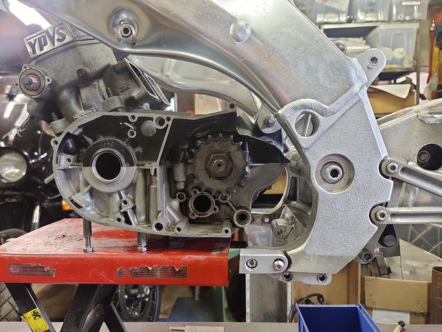 IMG_20220529_170909 IMG_20220529_170909When i had the bike on it's wheels i noticed that there was a decent amount of sag in the rear suspension. So i was thinking, when i counter act the sag with adjusting the rear height. The engine comes also straight(er). Also one thing i still need to do with the frame is to make a cut out for the chain in the lower frame cross member. |
|
|
|
Post by joossio on Aug 2, 2022 21:07:40 GMT 1
Nice project. I must say though that unless its the angle of the pics the motor and drive sprocket looks like it would be better positioned a little lower for the chain run to reduce squat under load and canted forward so that the case joint is parallel with lower rails.. As a guide the crank, output shaft and swingarm pivot should be on the same horizontal plane and the rear wheel spindle coming up to that somewhere around mid to 3/4 suspension travel.. I worked with the info; output shaft, swingarm pivot and rear wheel axle in line under load If I also should take the crank in account the engine would tilt back even further. Im due to head off for work. I will do my homework in the meantime to double check everything. Thanks and you will hear from me soon. |
|
|
|
Post by dusty350 on Aug 2, 2022 21:46:05 GMT 1
Hi Welcome to the forum  Nice project. Look forward to your progress Dusty |
|
|
|
Post by Tobyjugs on Aug 2, 2022 22:51:14 GMT 1
Hello Joost welcome to the forum. Im glad you joined. I think you have done a good job so far. Don't worry about the critiscism as it can be very helpfull, most forum members only mean good. (some of the above does sound a bit conflicting  ) I was impressed when you made your tools to be able to fabricate the other parts of the bike and chassis that you have not posted here. I am looking forward to seeing this one being built. I also have a bit of critiscism why don't you delete this thread and post it in the correct section on the Restorations page  Maybe Dusty can help. |
|
|
|
Post by veg on Aug 2, 2022 23:08:18 GMT 1
Great project interesting to see how it develops and as Tony sys get it moved into the projects area. 👍
|
|
|
|
Post by joossio on Aug 2, 2022 23:20:04 GMT 1
Hello Joost welcome to the forum. Im glad you joined. I think you have done a good job so far. Don't worry about the critiscism as it can be very helpfull, most forum members only mean good. (some of the above does sound a bit conflicting ) I was impressed when you made your tools to be able to fabricate the other parts of the bike and chassis that you have not posted here. I am looking forward to seeing this one being built. I also have a bit of critiscism why don't you delete this thread and post it in the correct section on the Restorations page Maybe Dusty can help. What other stuff would you like me to show them here? You mean all the rear suspension bits that i did'nt have and had to fabricate myself? I have asked Dusty if he could move it. |
|
|
|
Post by zed1015 on Aug 3, 2022 0:00:10 GMT 1
Thanks everyone for the reply, The engine has a possible tilt backward of a couple of degrees. This is how i started in the beginning IMG_20220529_170909When i had the bike on it's wheels i noticed that there was a decent amount of sag in the rear suspension. So i was thinking, when i counter act the sag with adjusting the rear height. The engine comes also straight(er). Also one thing i still need to do with the frame is to make a cut out for the chain in the lower frame cross member. The engine position in this pic looks nigh on perfect with what appears to be maybe a further 10mm drop needed to bring the case joint inline with the swingarm pivot center. |
|
|
|
Post by arrdy350 on Aug 3, 2022 6:38:18 GMT 1
Welcome to forum and great project 👍
|
|
crigar
Weekend rider

Posts: 88
|
Post by crigar on Aug 3, 2022 18:12:45 GMT 1
Bonjour à tous et excusez-moi s'il vous plait, je ne parle pas anglais.
L'alignement du pignon de sortie de boîte avec l'articulation du bras oscillant ne me semble pas une bonne solution.
Veuillez-voir ici : Effet de chaîne
Pour les bielles + 4mm il est important de choisir des pistons spéciaux avec axe décalé pour supprimer l'appui du piston sur le cylindre lors des mouvements de montée et de descente.
Google translation
Hello everyone and please excuse me, I don't speak English.
Aligning the gearbox output sprocket with the swingarm joint doesn't seem like a good solution to me.
Please see here: effet de chaîne
For connecting rods + 4mm it is important to choose special pistons with offset axis to eliminate the support of the piston on the cylinder during up and down movements.
|
|
|
|
Post by jon on Aug 3, 2022 18:16:29 GMT 1
Bonjour à tous et excusez-moi s'il vous plait, je ne parle pas anglais.
L'alignement du pignon de sortie de boîte avec l'articulation du bras oscillant ne me semble pas une bonne solution.
Veuillez-voir ici : Effet de chaîne
Pour les bielles + 4mm il est important de choisir des pistons spéciaux avec axe décalé pour supprimer l'appui du piston sur le cylindre lors des mouvements de montée et de descente.
Google translation
Hello everyone and please excuse me, I don't speak English.
Aligning the gearbox output sprocket with the swingarm joint doesn't seem like a good solution to me.
Please see here: effet de chaîne
For connecting rods + 4mm it is important to choose special pistons with offset axis to eliminate the support of the piston on the cylinder during up and down movements.
I fail to see how both of those statements are related in any way? Jon |
|
crigar
Weekend rider
Posts: 88
|
Post by crigar on Aug 3, 2022 18:31:27 GMT 1
Désolé le piston et la bielle +4 était pour un autre post
Sorry piston and connecting rod + 4 was for another post
|
|
|
|
Post by jon on Aug 3, 2022 19:32:47 GMT 1
The second statement is not really clear.
The correct terminology for ‘offset axis’ in this case is crown height.
The +4 stroke has nothing to do with this directly. It is the conrod length. Standard is 110mm. Some +4 cranks run 115mm conrods. Therefore some special pistons are available with a crown height of 23mm instead of 28mm. This corrects the height. The longer rods take some of the side loading off the piston, as it oscillates at a narrower maximum angle.
Jon
|
|
|
|
Post by zed1015 on Aug 4, 2022 8:42:16 GMT 1
Nice project. I must say though that unless its the angle of the pics the motor and drive sprocket looks like it would be better positioned a little lower for the chain run to reduce squat under load and canted forward so that the case joint is parallel with lower rails.. As a guide the crank, output shaft and swingarm pivot should be on the same horizontal plane and the rear wheel spindle coming up to that somewhere around mid to 3/4 suspension travel.. If I also should take the crank in account the engine would tilt back even further. You have either been given the wrong advice or have slightly misunderstood. With the frame set in a jig, the frame level and the steering castor angle correct in relation to the vertical axis ( in this case 25.5 degrees ) the engine needs to be mounted with the fixed points of the crank and output shaft on the same horizontal line as the swingarm pivot. Ideally the frame should be jigged off the steering head and not the fork axle to avoid frame movement and castor angle changes in relation to the engines horizontal line whilst the mounts are constructed. I usually use just the upper case half with a level slung to the crankcase joint for the most accurate way to align the centerlines. The location of the rear wheel spindle which is variable due to suspension sag, machine and rider weight ect etc can be ignored for engine positioning. Once built, the stance/attitude and height of the machine can be fine tuned by the use of adjustable suspension tie bars at the rear and if needed height adjustments to the front forks. The R1 forks can be internally lengthened by up to 32mm by the addition of a simple damper rod extension. I would also say that unless you need a full cradle for fairing mounts etc it's not actually needed and a side stand bracket could be brought off the lower right cradle mount. . |
|
|
|
Post by joossio on Aug 4, 2022 10:44:26 GMT 1
@zed1015 Thank you for your more detailed explanation. I'll will work out the details in the time I'm working on the ship. And when I'm home again try to improve the engine location. About the cradle, I need it for various things: - Engine regidity (especially when I want to. push to 100hp in the future) I'd rather have it build 'to' strong then give the engine the chance to flex. - Radiator mounting - Fairing mounts - Etc jonI found long stroke pistons. But just for now in only found pistons with 0.25 increments at MB-Design. Have only found Wiseco or Wossner pistons with 0.50 increments. |
|
|
|
Post by jon on Aug 4, 2022 13:28:13 GMT 1
jonI found long stroke pistons. But just for now in only found pistons with 0.25 increments at MB-Design. Have only found Wiseco or Wossner pistons with 0.50 increments. As I said before they are not “long stroke” pistons, they are “long rod” pistons. They were always only ever available in 0.5mm sizes. It’s only MBD that’s started offering 0.25mm sizes. When I bought mine off him he only did 0.5mm increments. Would have got away from STD to 0.75mm over on badly worn cylinders, but had to up it to 1mm over. Never mind a true 385cc. Jon |
|
|
|
Post by joossio on Aug 5, 2022 15:40:07 GMT 1
jonI found long stroke pistons. But just for now in only found pistons with 0.25 increments at MB-Design. Have only found Wiseco or Wossner pistons with 0.50 increments. As I said before they are not “long stroke” pistons, they are “long rod” pistons. They were always only ever available in 0.5mm sizes. It’s only MBD that’s started offering 0.25mm sizes. When I bought mine off him he only did 0.5mm increments. Would have got away from STD to 0.75mm over on badly worn cylinders, but had to up it to 1mm over. Never mind a true 385cc. Jon Try to search on both and tell me what gives you a better search hit haha  +0.25 pistons would be enough for me because the original Cilinders are barely out of spec. With small increments I can get more life circles out of the set. |
|


 )
) Maybe Dusty can help.


