|
|
Post by Tobyjugs on Nov 17, 2017 0:13:54 GMT 1
Tonight i measured my new pistons and rebored/honed barrels to record the the clearance. I am very glad i did they were both identical but had a clearance of +0.03 mm which is too small. The company is very good reputation in Holland so this was a bit of a surprise and just go's to show it's always good to double check things. I will make some pictures of the measuring tools when they come back after being corrected. Better too small than too big  |
|
|
|
Post by Tobyjugs on Dec 15, 2017 16:08:31 GMT 1
Finally got my barrels back and now at the correct size Luckily for me they were honed too small and not too big. These pistons are the ypvs type. There has been a lot of discussion wether to remove the middle tang or not? Below is a small film to help you decide which action to take. Click on the picture to see the film 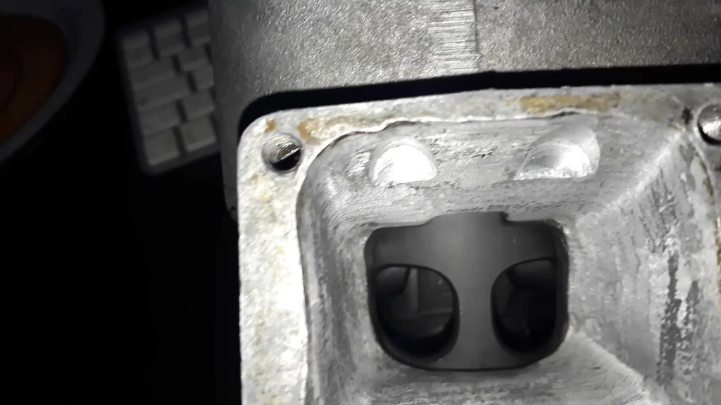 Bumping Piston Bumping Piston by Tony Macfarlane, on Flickr |
|
|
|
Post by Tobyjugs on Jan 3, 2018 21:36:18 GMT 1
Managed to find a bit more time so i have filed the middle tang away and now there is no bumping noise. 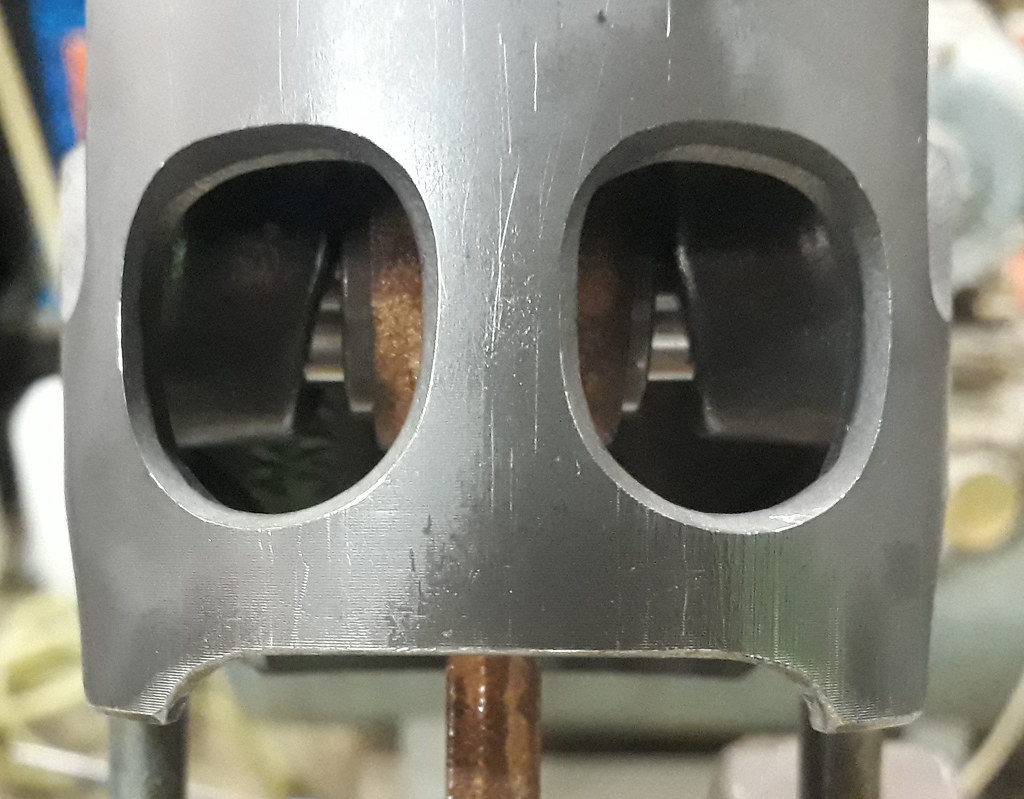 I made some more inspections and found some more little problems. First i found a cylinder head stud slightly stretched. 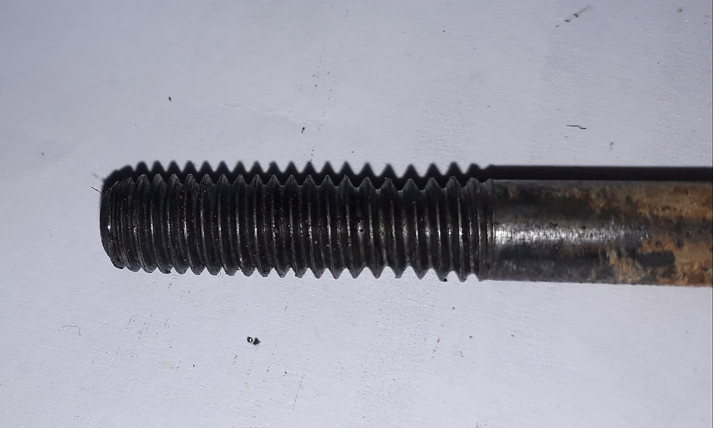 Secondly i found a big dig mark in the under side of the barrel where some one has probably used a screwdriver to loosen the barrel from the block  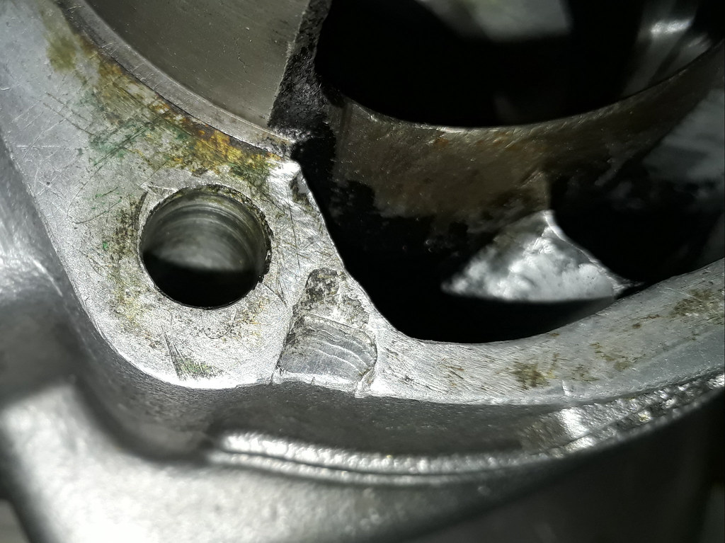 |
|
|
|
Post by lrcarl on Jan 3, 2018 21:50:07 GMT 1
Hi tony definitely a screwdriver looks like 3 good hits
Carl
|
|
|
|
Post by Tobyjugs on Jan 3, 2018 22:00:06 GMT 1
Hi tony definitely a screwdriver looks like 3 good hits Carl I think the man used the same screw driver to do the porting  To be fair the rest of the motor was well put together and even Kees couldn't blow this one up! |
|
|
|
Post by Tobyjugs on Jan 4, 2018 14:49:27 GMT 1
I thought i would do some more measuring and checking today. If any one is interested in any aspect of a check make a comment and i will go deeper into it.
To do some of the following checks i will need the cylinder head nuts/bolts. Through previous experience i now run a tap through these nuts/bolts to clear out any rust or crud that has accumulated over the years and its also a way of checking that they are good to use.
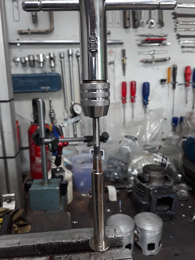
The next thing i did was to measure the ring gap of all the piston rings in their allocated barrels (sorry no picture). The pistons were then fitted to the conrods and two 0.50mm base gasket were placed in position. Next the barrels and head was fitted.
The head was tightened to 25 nm but not in the usual sequence.
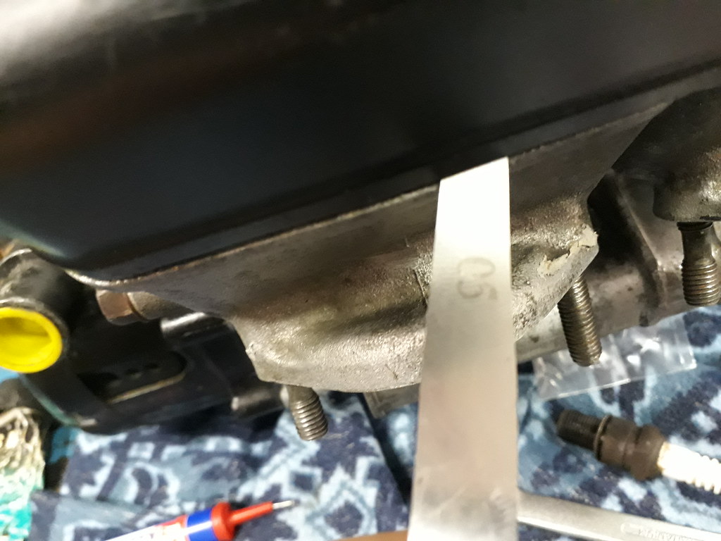
This cylinder head has loose combustion domes and i feel that the domes should be tightened in a cross form and not from the middle out. The sequence i used is 1,8,2,7,3,5,4 and 6. Because this is new i checked the free area outside the combustion domes and found i had 0.05mm in between the domes and 0.08mm space on the outside of the domes. Hopefully with the right sealant this will seal ok.
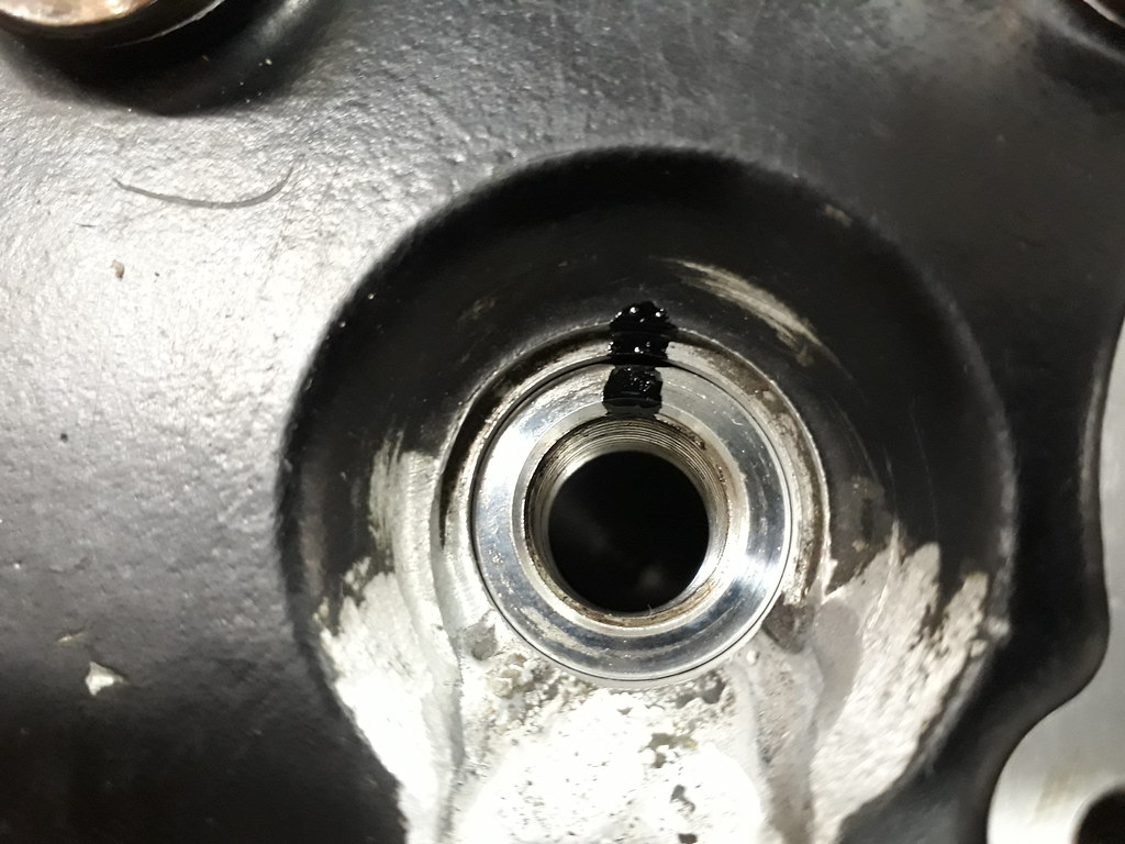
After checking the cylinder head clearance i marked the top part of both domes with a black stripe and screwed in two spark plugs very tightly and tried to turn the domes. I tested this because i was thinking about pinning the domes to stop them turning but i was told there was no need to do this (me being stubburn i guess). I couldn't turn the domes.
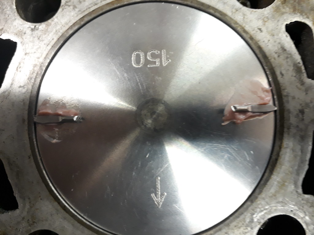
The cylinder head was removed and i checked the squish clearance with some solder, i was very happy to see that all the squashed solder was very uniform in shape. This means the squish ring has the same profile as my piston crown. The sqaushed pieces of solder were the same thickness for each cylinder but there was a difference of 0.05 mm. The squish band for these domes is supposed to be 0.90mm and i have 0.90 and 0.85mm so i will fit a slightly thicker base gasket to bring both tolerances 0.10 mm bigger.
|
|
|
|
Post by 4l04ever on Jan 4, 2018 15:12:13 GMT 1
You can check the squish at the front and back too...then take an average.
|
|
|
|
Post by Tobyjugs on Jan 4, 2018 15:19:46 GMT 1
I will try that.
|
|
|
|
Post by 4l04ever on Jan 4, 2018 22:53:57 GMT 1
Doing 4 measurements will also make sure the combustion chamber is centred over the piston/bore.
|
|
|
|
Post by Tobyjugs on Jan 4, 2018 23:12:33 GMT 1
You can check the squish at the front and back too...then take an average. Hi Rob after the last measurement the base gaskets were adjusted and the squish height was checked again using 4 points as suggested by you  The heights were very even and there is a height difference of 0,04 mm between the two chambers using the four point method. I hope this height difference does not make too much of a difference. 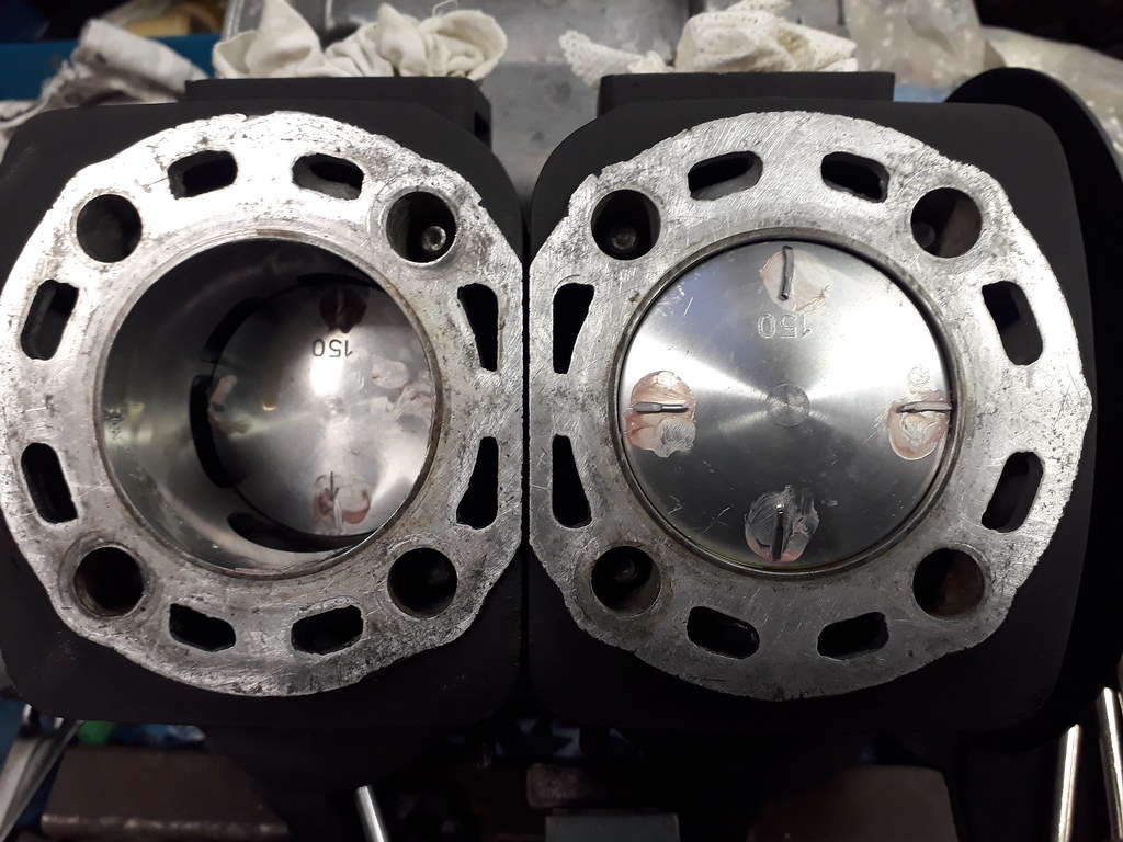 |
|
|
|
Post by jon on Jan 4, 2018 23:33:56 GMT 1
Hi Tobyjugs,
What are you using to ‘glue’ the solder to the top of your pistons?
I’ve always just inserted a twisted piece of soldier through the spark plug holes at various positions (‘of the clock’) then removed and measured?
Jon
|
|
|
|
Post by Tobyjugs on Jan 5, 2018 0:20:32 GMT 1
Hi Tobyjugs, What are you using to ‘glue’ the solder to the top of your pistons? I’ve always just inserted a twisted piece of soldier through the spark plug holes at various positions (‘of the clock’) then removed and measured? Jon Hi jon i am using a O-ring grease M55. If i was doing a quick check i would do what you suggest but there is no rush and this is a good way to check and adjust. |
|
|
|
Post by Tobyjugs on Jan 7, 2018 10:07:06 GMT 1
A couple more checks the the cylinders will be buttoned up. First thing i need to do is fix the two barrels tightly in place (not King Kong style). So Tobyjugs Top Tip of the Day is use a couple of YPVS cylinder head nuts with some flat washer to hold your barrels in place. 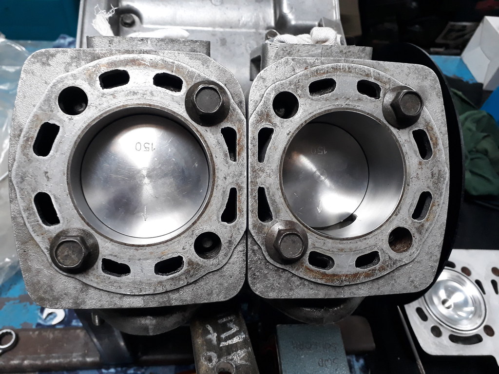 Once this is done a timing plate was fitted to the crankshaft to determine TDC of the piston on the fly wheel side and then check TDC on the other piston to see that the crankshaft is in phase. I found a discrepancy of just 1/5 of a degree which is could be my measuring or the crankshaft. Either way it's a small tolerance not to be worried about. Now my timing plate is in place (is that the correct words?) i can now measure the port durations open/closed for the barrels. 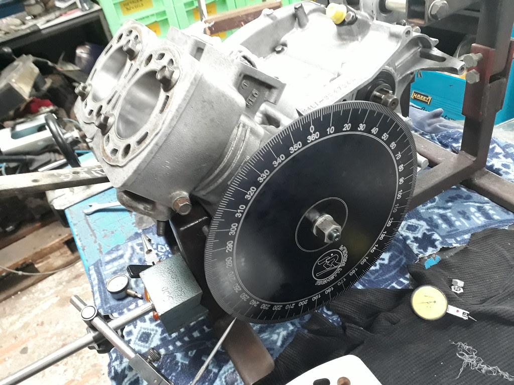 The cylinder head will now be fitted and the next test will be to pressure test the cooling water space as the cylinder head is not standard and the induction/combustion space.
|
|
|
|
Post by Tobyjugs on Jan 7, 2018 15:25:59 GMT 1
Now all the checks are finished i thought i would document them for the people that might find it interesting. Crankshaft
| Flywheel | Gearwheel | | Crankshaft Runout fitted | 0.03 mm | 0.05 mm | Big end axial clearance new
| 0.80 mm | 0.75 mm | | Big end axial clearance adjusted | 0.45 mm | 0.50 mm |
The nominal size of the pistons are 1.50 mm oversize and the make is PROX
| Flywheel | Gearwheel | | Piston/Bore clearance | 0.05-6 mm | 0.05-6 mm
| | Top piston ring gap | 0.25 mm | 0.25 mm | | Bottom piston ring gap | 0.30 mm | 0.30 mm |
The base gaskets fitted to this engine are 0.60 mm thick
| Flywheel | Gearwheel | | Compression ratio (uncalc) | 12.5/1 | 12.5/1 | | Squish band height | 0.94 mm | 0.98 mm |
(open/close) Exhaust port 197 deg duration Inlet Boost 128 deg duration Transfer port 130 deg duration Back Lash
Primary drive gear wheel 92 primary driven gear wheel 62B Back Lash = 154 Average clearance between gear wheels = 0,08 mm |
|
|
|
Post by simon998 on Jan 8, 2018 14:46:04 GMT 1
Cracking thread this. I feel like I've learned something! I'm away to read more on porting 2-strokes.
|
|
|
|
Post by Tobyjugs on Jan 8, 2018 21:26:18 GMT 1
Cracking thread this. I feel like I've learned something! I'm away to read more on porting 2-strokes. Thanks for the comments simon. Two stroke porting is still a black art for me, but if you measure and log specs you will build up a picture of what works for yourself. I have also noticed it is better to check the components as well as they are not always what it seems. On this build the cylinders got sent back for re honing as they were too tight and there was a bit of a hoohah with the crankshaft as well. |
|
|
|
Post by earthman on Jan 8, 2018 21:33:54 GMT 1
Cracking thread this. I feel like I've learned something! I'm away to read more on porting 2-strokes. +1.  |
|
|
|
Post by Tobyjugs on Jan 8, 2018 22:37:56 GMT 1
The leakdown test has been carried out and the new rubber carb boots were leaking. This is a bit disapointing as after i have run the engine in a bit i was planning on changing the standard reed blocks and Chariot manifold for my modified reeds and manifold to see what difference it would make. If i'm not careful it can run lean if they leak. In the picture below i have marked the areas which was leaking with blue arrows. 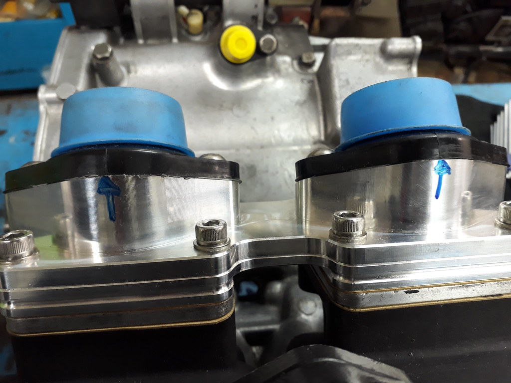 I haven't pressure tested the cooling water space yet as i have seen a more niggling problem to solve with the temperature sensor. I had planned on placing the sensor behind the inlet manifold but i forgot to take into account how much the sensor actually sticks out doh! 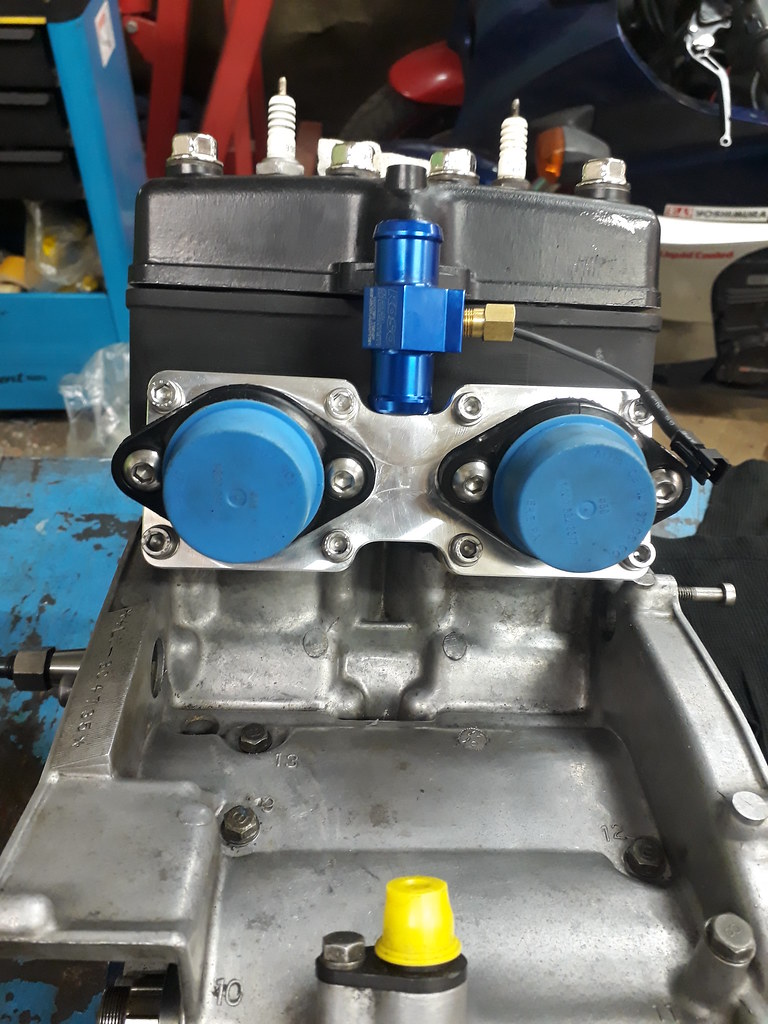 So plan B is either make a new flange on the entrance to the cylinder head and fit the sensor there. The advantage of this is i can remove the sensor with minimal work. Another option easier to make (less hand work involved) would be to extend the pipe that fits into the engine side casing and fit the sensor there. The advantage of this would be to give me the option of also fitting a pressure sensor (if wanted). The disadvantage would be the extra work involved in removing the pipe to revert to original 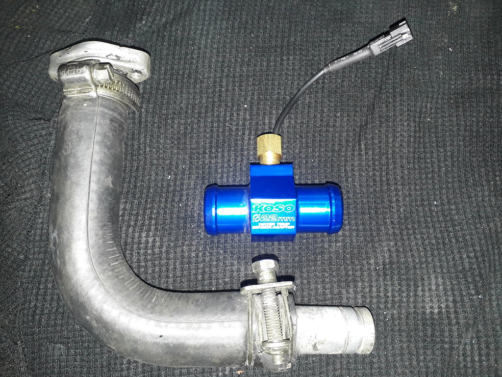 Theres nothing like a bit of brainstorming so if anyone has any suggestions i would be very happy to hear them  |
|
|
|
Post by 4l04ever on Jan 8, 2018 23:23:45 GMT 1
It looks like the standard hose won't work anyway, so may need to modify the head inlet, so it points to the left. You can then run a longer hose across the bottom under the two carb inlets and up the left side with the sender fitted on the vertical rise, then a 90 degree silicon hose to the new inlet on the head.
|
|
|
|
Post by 4l04ever on Jan 8, 2018 23:35:20 GMT 1
I have emailed you a pic of the plumbing on my LC.
|
|
|
|
Post by Tobyjugs on Jan 8, 2018 23:37:41 GMT 1
Hi Rob thank you very much definitely food for thought  |
|
|
|
Post by 4l04ever on Jan 8, 2018 23:37:46 GMT 1
If the standard pipe will still fit, you could make a custom top fitting like the standard fitting to the head, but longer with a thicker section on the front face with a hole drilled and tapped for the sender, then chop a bit out the standard hose.
|
|
|
|
Post by Tobyjugs on Jan 8, 2018 23:39:47 GMT 1
Yes that was what i was trying to say for the top option
|
|
|
|
Post by Tobyjugs on Jan 10, 2018 0:50:36 GMT 1
Well chaps this little puzzle has been solved.  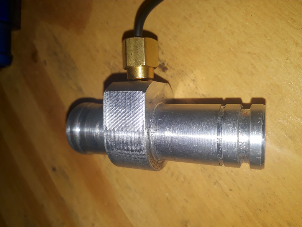 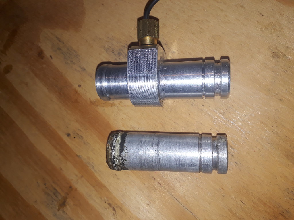 This morning i gave Pieter from PS Tuning a call to ask if he could make me a fitting, he said yes and meet him at 19:00 tonight, which i did. He started straight away on the lathe and i made some fresh coffee and prepared the milling machine for him. One and a half hours later it was finished and i was grinning like a Cheshire cat knowing i could get on with building the engine up. So thats a big thumbs up for Piet. This fitting is only good for a 4LO engine and the best way would be to make a fitting as suggested by rob in our little brainstorming conversation. A fitting that fits the top of the cylinder head could be used on both types of block. I will make one later as i will be wanting to see whats happening with the different make heads i have for the YPVS type engines. Below is some bits i have been trying to get my hands for a while now. It's for another little project. Pieter has also given me this so i can make some measurements and checks. 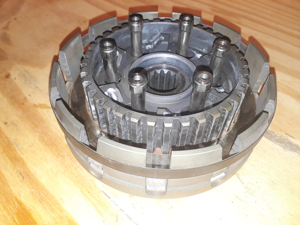 |
|
|
|
Post by headcoats on Jan 10, 2018 12:09:12 GMT 1
What will you use to repair the "screwdriver" damage on the gasket face ?
I have a dink in one of my barrels too which I need to look at , not as bad but think it needs filling with something ??
|
|
|
|
Post by simon998 on Jan 10, 2018 14:17:57 GMT 1
Liquid metal could work if it's cleaned and etched. I used it on my engine casing and it still holding up. Doesnt look great though so I'm still looking for a replacement.
|
|
|
|
Post by Tobyjugs on Jan 10, 2018 19:51:29 GMT 1
Yes that's exactly what i used, it is called Wencom the reason i use this stuff is because i can get it for free as we use it in work. If you press on this LINK you can see where i have used it previously and it is still good. |
|
|
|
Post by Tobyjugs on Jan 10, 2018 20:05:13 GMT 1
My temperature sensor is now fitted so i thought i would show you 2 pictures of it. 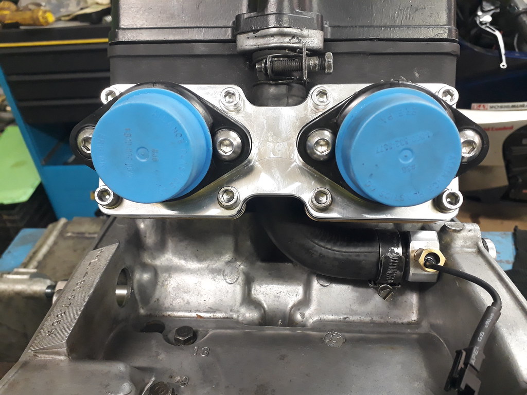 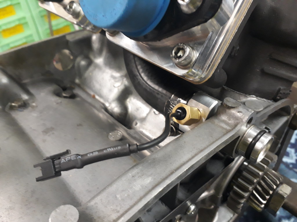 |
|
|
|
Post by wallcraft on Jan 10, 2018 21:24:56 GMT 1
Lovely work, can i have one please 😊
|
|
|
|
Post by rigga on Jan 10, 2018 21:40:31 GMT 1
Excellent solution, great reading threads like this .
|
|