|
|
Post by bryan on Dec 2, 2009 0:30:09 GMT 1
Hi all, been on the other forum most of the time and have a thread there, but while its down I need some guidence. Got this far. 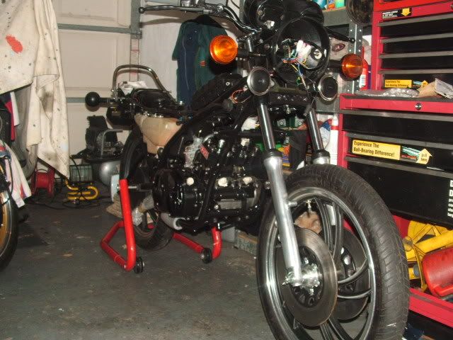 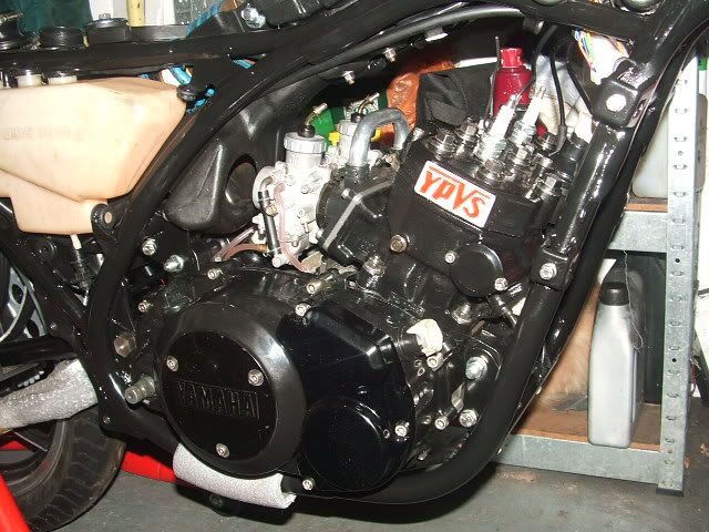 Just been going through the ignition, which is made up from the following, F2 stator and rotor, all tested ok. LC coil tested ok. LC CDI, not known if it's ok yet, but will test it on the other LC. Would these work together, or do I need an F2 CDI and coil. I will have an F2 cdi once the other forum is up again, cant contact the person at the moment. I have a new .7ohm Dyna coil which I may use but wont fit in the origonal location and I have an air box, so it cant go there unless I go to individual filters. I will be going to a Zeeltronic all in 1, but not got any money spare at the moment. |
|
|
|
Post by Norbo on Dec 2, 2009 10:37:49 GMT 1
you will need a F2 CDI mate it wont work with a LC one . it should still be ok with the HT coil but would be better with the dyno coil i run one on mt F2 and they are Ace.
If you get stuck for a CDI i have a couple of new unrestricted CDI's to run with no setting up or mods just wire in and go. Bit of a wast if you are going for the all in 1 at some point though .
.
|
|
|
|
Post by midlifecrisisrd on Dec 2, 2009 16:11:43 GMT 1
you will need a F2 CDI mate it wont work with a LC one . it should still be ok with the HT coil but would be better with the dyno coil i run one on mt F2 and they are Ace. If you get stuck for a CDI i have a couple of new unrestricted CDI's to run with no setting up or mods just wire in and go. Bit of a wast if you are going for the all in 1 at some point though . . Hi, what do you mean by unrestricted cdi? I've an LC2/rgv hybrid running 4CE electrics, will ideally be looking at changing in the future to a better one. Sorry to jump in. Steve. |
|
|
|
Post by bryan on Dec 2, 2009 17:16:50 GMT 1
you will need a F2 CDI mate it wont work with a LC one . it should still be ok with the HT coil but would be better with the dyno coil i run one on mt F2 and they are Ace. If you get stuck for a CDI i have a couple of new unrestricted CDI's to run with no setting up or mods just wire in and go. Bit of a wast if you are going for the all in 1 at some point though . . Why wont it work with the CDI norbs, Im not worryed about the PV at this point just want it running. I have checked the Zeeltronic wireing diagrams and both LC/YPVS manuals and the only differance for the power to the CDI is the low speed winding has a black wire on LC and green on the F2. I have an F2 CDI with no connectors comming to me for £20, which will do untill I get a Zeeltronic all in 1 from you, or I just need the Zeeltronic RZ CDI and control it with my VCDI off the LC, so I dont want to spend on anything else. Which Dyna coil did you use, I got a pair of the blue 0.7ohm DC9s, which I cant fit with a standard airbox so swapping for the minature series 0.5ohm DC11s. |
|
|
|
Post by bryan on Dec 2, 2009 17:22:17 GMT 1
you will need a F2 CDI mate it wont work with a LC one . it should still be ok with the HT coil but would be better with the dyno coil i run one on mt F2 and they are Ace. If you get stuck for a CDI i have a couple of new unrestricted CDI's to run with no setting up or mods just wire in and go. Bit of a wast if you are going for the all in 1 at some point though . . Hi, what do you mean by unrestricted cdi? I've an LC2/rgv hybrid running 4CE electrics, will ideally be looking at changing in the future to a better one. Sorry to jump in. Steve. The F2 CDI (1UA) has about 3-4deg less advance at 9000rpm, so looses some power over the F1 (52Y) at the top end. |
|
|
|
Post by Norbo on Dec 5, 2009 10:53:12 GMT 1
All i can say is i have never seen a LC CDI fitted to a YPVS bike.
midlifecrisisrd:
I have a couple of trick Digital CDI's just for the YPVS that plug straight in. You cant do this with the standard Zel CDI's I had theys made up special they offer more revs and faster pick up with no other mods then plug in and no rejetting.
I had them made becourse YPVS CDI's are getting harder and harder to get and you need to get the correct CDI for the Stator but i figgered with theys they will fit to any YPVS and will offer more power as well and ofcourse be new.
|
|
|
|
Post by bryan on Dec 5, 2009 13:22:16 GMT 1
All i can say is i have never seen a LC CDI fitted to a YPVS bike. midlifecrisisrd: I have a couple of trick Digital CDI's just for the YPVS that plug straight in. You cant do this with the standard Zel CDI's I had theys made up special they offer more revs and faster pick up with no other mods then plug in and no rejetting. I had them made becourse YPVS CDI's are getting harder and harder to get and you need to get the correct CDI for the Stator but i figgered with theys they will fit to any YPVS and will offer more power as well and ofcourse be new. whats the curve on these norbs, 52Y or 1UA, and how much are they. I dont have any other CDIs here to use at the moment, so trying it with an LC one just to see if I can get it running. I cant see why it wouldent work as it has the same inputs and outputs. |
|
|
|
Post by Norbo on Dec 7, 2009 12:45:13 GMT 1
like climing a steep hill . I had a red line at 12 so people dont blow the bike up but becides that they are an open rev CDI. They run at £170
|
|
|
|
Post by midlifecrisisrd on Dec 8, 2009 16:39:58 GMT 1
like climing a steep hill . I had a red line at 12 so people dont blow the bike up but becides that they are an open rev CDI. They run at £170 Think I'll have to save for something like that. Don't think my 4ce cdi will be up to much. Will the trick ones be compatible? 4ce has an extra wire and I take it there will be no plugs so just connect up yourself ( not a problem, spark to trade ). Also how much does the zeel kit come in at, like the sound of conntrolling the pv's as well. Steve. |
|
|
|
Post by bryan on Dec 8, 2009 17:43:59 GMT 1
all in 1 is £240 plus £55 for the hand held programer, of the 3 individual units are £20 cheaper. The all in 1 is easyer to install as its just a single unit incorperating the programable CDI and programmable powevalve controller. click on norbos site, homepage.ntlworld.com/ultimatelccrazy/go to ONE STOP LC SHOP, then click on YPVS parts, click on the 3 pics to the right of YPVS trick bits page and scroll down 3/4 of the page. Ther is a bar switch to swap between two curves too. here is a wiring diagram from Boruts site. www.zeeltronic.com/manuals/RZ_wiring_PCDI-10V.pdf |
|
|
|
Post by bare on Dec 8, 2009 18:40:42 GMT 1
If memory serves the venerable LC cdi should work as it's a Very Mild (barely a curve) curve.
All you will lose is performance... assuming the thing works with your flywheel statror/pickup.
The zeel unit is "fine' by any yardstick but in inept hands it's far easier to explode your motor , given the unrestriucted ability to input foolish ignition parameters.
Don't be reving yer pore crankshaft past 10.5 k rpms (on an accurate tach , not the useless oem one ;-) ...if you want to ride home.
|
|
|
|
Post by bryan on Dec 8, 2009 22:05:31 GMT 1
already have the rev limit set at 10,500rpm on the LC.
I will get atleast a Zeeltronic CDI-RZ1 to fit on this bike and remove the VCDI from the LC and program the YPVS curve into it.
I have looked at the wiring for both the LC and YPVS on the Zeeltronic pages and the only differance is the black wire on the LC low speed winding is Green on the YPVS, so connecting these together should supply the correct voltage to the CDI.
The red wire is the high speed winding and brown is the common wire on both.
I know I wont have the YPVS system working, but I want to get it running ASAP.
Worst case is Ill remove the LCs stator and fly wheel and use that to get it running, more likley is Ill sent Norbo a cheque for the Zeeltronic YPVS CDI as its only £70 and its a new one.
|
|
|
|
Post by bryan on Dec 11, 2009 1:54:42 GMT 1
right, had a play with the bike tonight.
I removed the CDI and coil to try on my LC, they all worked including the plug caps, so thats not the reason it wouldnt fire.
Checked the kill switch, works correctly.
I then had a look through the 2 wire diagrams for a Zeeltronic PCDI-10 fitted to both a YPVS and LC.
The extra pick up wire (white/green) is not used on an LC, and I had left it free. However, on a PCDI-10 its connected to the black wire.
I thought I would give it a try with the white/green wire connected to the black wire, gave it a kick and it started first time but ticks over very fast, even though sliders are all the way down.
Now I know the YPVS stator runs at about 34deg static advance so that could be the reason, as I havnt pulled the VCDI off the other LC yet so I can retard it to 20deg.
I will be sorting out a proper YPVS CDI of some kind as soon as I can, just happy to hear it running tonight.
|
|
|
|
Post by dredge3 on Dec 11, 2009 22:37:37 GMT 1
Hope you get it sorted mate  |
|
|
|
Post by bare on Dec 12, 2009 3:52:32 GMT 1
Suggest you use a "stick on" Degree wheel on the Flywheel.
Setting 0 at the exact TDC position, using a stop or dial gauge and then using a strobe, Double Check the running engine to see EXACTLY where the Thing actually fires.. I've found a 4 degree advance errr... discrepancy.. on my PCDI 10 (s)
And it revvved kinda high... until I discovered and compensated by retarding the Entire curve the suspect 4 degrees. thereby getting the thing to spark at exactly 20d @ 2000rpm to match the programmed setting/display on the remote.
Bit of a puzzle.. still.. as to Why? it does this... and No! the crank is Not wonky.
|
|
|
|
Post by bryan on Dec 12, 2009 5:40:21 GMT 1
Im allready up on that Bare, but thanks. I have marked my flywheel like this, 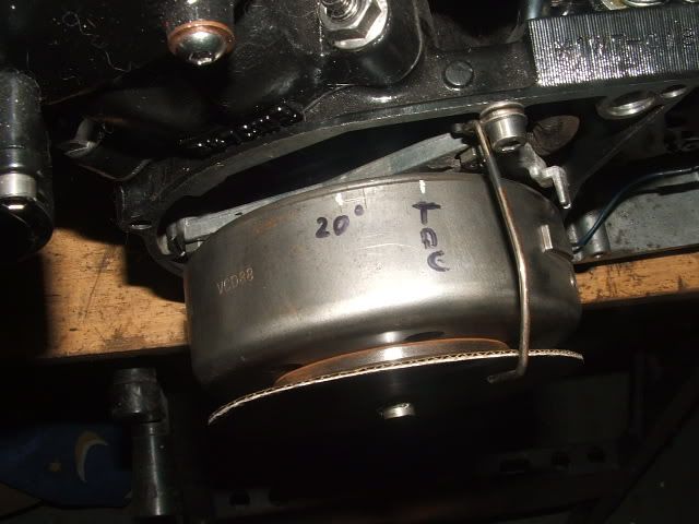 I have a 20deg flat curve already in the VCDI, then with the strobe light adjust the static timming on the VCDI till it lines up. Bingozingo.  Did I understand this correctly, you changed your whole curve or did you correct it with the static value? Im still waiting on getting in contact with someone who has an F2 CDI with no connectors on it to use, if I get no joy I will get a Zeeltronic CDI-RZ1 from Norbo, but I would like to wait and get an all in 1 and leave the VCDI on the other LC. Fitted the ultra lower pair of Renthal bars tonight and its sorted the high reving out, the throttle cabel was a bit too tight with the higher rise bars fitted. Im happy to have got it running and got some fresh oil through it, as its been sitting for a year since I built it. |
|
|
|
Post by nikfubar on Dec 13, 2009 2:42:39 GMT 1
Bryan Sorry to jump in on your thread but you seem to know about CDI wiring. I have just fitted a 52Y cdi to my F2 and down loaded the wiring diagram which says match all the colours and then connect the Black/White to red for the kill switch. Done this and all works but when you look at the manual schematics the coil windings for the red, brown & green wires are in a different order  does this matter. Started a thread on this in help and advice but no response yet. Any help would be much appreciated. If i can be sure the 52Y cdi is working properly i will have a spare 1UA F2 cdi if it's any help Cheers Nick |
|
|
|
Post by bryan on Dec 13, 2009 6:43:24 GMT 1
I belive the black/white is different, as it goes to the red/white on the F1/N1 stator, but to its own black/white wire from the CDI on the F2, which you dont now have on the 52Y CDI. I have a link to a page that explains it, not sure if you have it already. domlnator.tripod.com/id25.htmlThis is the important bit. One can use the 85 (52Y- 50) CDI with the 84 or 86+ models. To connect an 85 cdi to an 86+ one connects the same colors and also put the black-and-white cable of the wiring harness to the black-yellow cable of the CDI. A second possibility is, black-and-white cables to the red cable to the CDI to also put (it functions both). From the manual the black/white is kill switch and black/yellow is pulse for the YPVS controler, so dont see why you would connect them together. It looks like the black/white to the red would be the correct choice. If it works as you have it, they why change anything. Im sorted with the CDI now thanks, tracked the bloke down through the Yamaha Past Masters Racing forum. I would assume the wires from your stator are the same colours, if you check the red to brown wires (high speed winding) it should be about 3.6-4.5 ohms, and the brown to green (low speed winding) 128-193 ohms. This will confirm the wires from your stator are the same as the F2, as I dont know for sure. |
|
|
|
Post by bare on Dec 13, 2009 19:30:53 GMT 1
I used the Curve retard option on the remote to retard the ''Entire Curve'' 4 degrees.
As for reason still unknown the PCDI thing(s) want to run at 4 degrees MORE advanced than the Remote reads or is set at.
Note that the 52y-50 CDI is the SAME (31K) curve that is the first curve that the PCDI comes 'preloaded with, IE: it's at 20 D @2k rpms and IS accurate when plugged in. and strobed.
My issue is with the obvious fact that Both of my PCDI's (Borut sent me a replacement.. which I will return to him.. Once.. I figure out why this is happening)
do this 4 degree advance error..Coincidence is unlikely
|
|
|
|
Post by slinger on Dec 13, 2009 20:35:07 GMT 1
Im allready up on that Bare, but thanks. I have marked my flywheel like this, I have a 20deg flat curve already in the VCDI, then with the strobe light adjust the static timming on the VCDI till it lines up. Bingozingo. Did I understand this correctly, you changed your whole curve or did you correct it with the static value? Im still waiting on getting in contact with someone who has an F2 CDI with no connectors on it to use, if I get no joy I will get a Zeeltronic CDI-RZ1 from Norbo, but I would like to wait and get an all in 1 and leave the VCDI on the other LC. Fitted the ultra lower pair of Renthal bars tonight and its sorted the high reving out, the throttle cabel was a bit too tight with the higher rise bars fitted. Im happy to have got it running and got some fresh oil through it, as its been sitting for a year since I built it. Once you set your static that's it, I'm surprised it's only 20 degrees mind. But after that just program it by the hand held and as long as the static is correct your be programming it real time. Do you need some maps? Glyn |
|
|
|
Post by slinger on Dec 13, 2009 20:38:45 GMT 1
I used the Curve retard option on the remote to retard the ''Entire Curve'' 4 degrees. As for reason still unknown the PCDI thing(s) want to run at 4 degrees MORE advanced than the Remote reads or is set at. Note that the 52y-50 CDI is the SAME (31K) curve that is the first curve that the PCDI comes 'preloaded with, IE: it's at 20 D @2k rpms and IS accurate when plugged in. and strobed. My issue is with the obvious fact that Both of my PCDI's (Borut sent me a replacement.. which I will return to him.. Once.. I figure out why this is happening) do this 4 degree advance error..Coincidence is unlikely That's a proper strange one Bare I've fitted over ten of these now and never had that problem. Would be good to here what is coursing it. Glyn |
|
|
|
Post by bryan on Dec 13, 2009 22:49:22 GMT 1
Im allready up on that Bare, but thanks. I have marked my flywheel like this, I have a 20deg flat curve already in the VCDI, then with the strobe light adjust the static timming on the VCDI till it lines up. Bingozingo. Did I understand this correctly, you changed your whole curve or did you correct it with the static value? Im still waiting on getting in contact with someone who has an F2 CDI with no connectors on it to use, if I get no joy I will get a Zeeltronic CDI-RZ1 from Norbo, but I would like to wait and get an all in 1 and leave the VCDI on the other LC. Fitted the ultra lower pair of Renthal bars tonight and its sorted the high reving out, the throttle cabel was a bit too tight with the higher rise bars fitted. Im happy to have got it running and got some fresh oil through it, as its been sitting for a year since I built it. Once you set your static that's it, I'm surprised it's only 20 degrees mind. But after that just program it by the hand held and as long as the static is correct your be programming it real time. Do you need some maps? Glyn Thats not the static advance the F2 stator has, its something like 34deg I think. This is to set the static advance setting on the Zeeltronic stuff, tells it how advanced the back plate is. You program a flat 20deg curve on the CDI, then use a strobe and adjust the static advance setting untill the 20deg mark lines up with the backplate. |
|
|
|
Post by bare on Dec 14, 2009 3:58:32 GMT 1
Correct! Then you notice that the thing is actually producing spark at 24 degrees (by the Strobe) instead of the 20 degrees the Remote (and what was pgm'd in) indicates.
SO!?? why is my engine seeming to need 38 degrees Static when everyone elses' is at 34 or more precisely at 34.5.?
I've asked this before but no one has provided answer (mine is a "87 1WV numbered unit. A felow from Italy also claimed that his "R" used 37.5 degrees static to work 'as advertised.
There might be something with the 'later' engines' design ? but it's a wee bit disconcerting when no one, not even the Ign 'maker' knows anything about this.
Total engine teardown is in order regardless, now that my long awaited TSS bespoke P valves are in hand.
But it's below 0 Celcius (Yup! even here in the Tropical Belt of Canada) So actual work in my unheated garage is temporarily ? on hold :-)
|
|
|
|
Post by nikfubar on Dec 14, 2009 10:20:38 GMT 1
[quote I would assume the wires from your stator are the same colours, if you check the red to brown wires (high speed winding) it should be about 3.6-4.5 ohms, and the brown to green (low speed winding) 128-193 ohms. This will confirm the wires from your stator are the same as the F2, as I dont know for sure.[/quote] Thanks for that checked the Haynes manual and both the N & F2 stators use the red to brown for high speed winding & brown to green for low speed winding so all is ok ;D What confused me is when you look at the wiring diagrams it shows a different layout for the colours to the windings  |
|
|
|
Post by bryan on Dec 14, 2009 17:44:24 GMT 1
I think you are reading too much in to the diagram of the stator Nick, I noticed that but knew the colours and which was the common wire. Its working correctly, so more than likely is wired correctly.
|
|


 does this matter. Started a thread on this in help and advice but no response yet.
