|
|
Post by bezzer on Nov 3, 2018 23:08:17 GMT 1
All looking good Al, Good to hear the shift mods have paid off 👍🏻. Your pics are a great reference source.
A question: Have your cases been vapour blasted?, not sure which way to go with mine?.
|
|
|
|
Post by dusty350 on Nov 3, 2018 23:08:39 GMT 1
Looking good Al - simple compared to that Rover engine !! Did you sort the dampers for the clutch basket ? Dusty  |
|
|
|
Post by alankelly on Nov 3, 2018 23:16:37 GMT 1
Hi Dusty
Yes that engine was a bit of a beast
Yes dampers all sorted as got from Norbo with the standard Matika basket as you suggested 👍
Funny thing was my old dampers were the same D shape as in your earlier build?
Catch up soon
Best wishes Al
|
|
|
|
Post by alankelly on Nov 3, 2018 23:20:32 GMT 1
Hi bezzer
Yes they were vapour blasted but not knowing the process well I asked only the outside to be done in case the cleaning process damaged any critical bearing bores as once buttoned up the internals are not on show
Best wishes Al
|
|
|
|
Post by dusty350 on Nov 3, 2018 23:35:10 GMT 1
Hi The Lc dampers are all "D" shaped. The Pv baskets seem to have the round dampers. Not sure if all your dampers are the same size. If you have 4 large and 4 small, like I have gone for this time, the bigger damper sits on the left of the pair, and the smaller on the right. Don't know how critical that is but that's how Yamaha fitted them  Dusty |
|
|
|
Post by marsbar350 on Nov 3, 2018 23:35:26 GMT 1
hi alan just noticed the washers under the neutral switch cover just make sure the chain will pass as its crammed for room around there |
|
|
|
Post by alankelly on Nov 3, 2018 23:52:47 GMT 1
Hi marsbar
Thanks for the advice
I addd the washes to stop the screws splitting the switch
All look good so far as screws are well below chain sprocket drive but will still check on putting ending back is
And yes it is a it crammed as I had fitted a one off hydraulic cylinder that takes more space than the normal screw cam arrangement
Many thanks in advance
Best regards Al
|
|
|
|
Post by skint on Nov 4, 2018 20:33:46 GMT 1
So, question is. Does vapour blasting the inside of the cases alter any critical measurements or can I go ahead and get mine done?
TIA
Paul
Great thread btw Allan.
|
|
|
|
Post by stusco on Nov 4, 2018 20:56:34 GMT 1
No
|
|
|
|
Post by dusty350 on Nov 4, 2018 21:32:38 GMT 1
Vapour blasting uses a non aggressive media suspended in high pressure water, so is a gentle process. It also helps to seal the "pores" of the aluminium, so it wont pick up dirt like a grit blasted surface will. You can adjust the level of finish with vapour too, so you can get a decorative finish that looks like the part has been sprayed with silver paint. The barrels and cases on this engine have been vapour blasted; 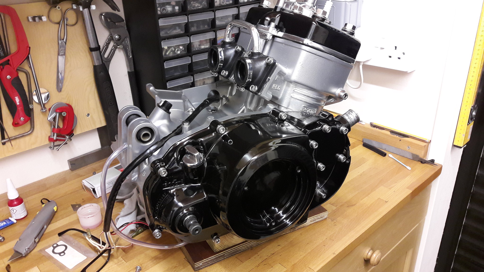 20170311_103629 20170311_103629 by David Miller, on Flickr Do put bolts in all your threadways though - saves the slurry getting in there, and always rinse well when you get the parts home to make sure all blast media has been washed away. Dusty |
|
|
|
Post by skint on Nov 5, 2018 10:01:00 GMT 1
Thanks dusty. Will put bolts in holes where neccesary and go ahead with peace of mind.
|
|
|
|
Post by 4l04ever on Nov 5, 2018 18:50:43 GMT 1
If the casings are not fully dried after blasting, you can get rust on any steel parts such as engine studs. You can protect them from surface rust with a spray of WD40 and wipe it off after.
Check with the blasting company to see if they fully dry the engine after blasting. If not, get the wD40 ready... :-)
|
|
|
|
Post by alankelly on Nov 6, 2018 21:16:46 GMT 1
Hi all, It getting colder in the shed these days, but just another quick update. After my small delay while I decided to convert the lower case shift drum assembly to a full needle roller bearing set up,.the engine build is finally progressing well During my initial inspection of all the main and output shaft bearings all seem OK , but as costs seem to have gone out the window :-( for this build decided to replace anything that looked "not right" so decided to replace all the main shaft and output shaft bearings, replaced a "brown / burnt"looking 3/4th gears on both shafts, and lastly replaced a dodgy "burnt" main shaft selector fork, as to replace any of these suspect items later would have been a pain, and finally with the new crank from PJ in place in the lower case, the final assembly looked the business. 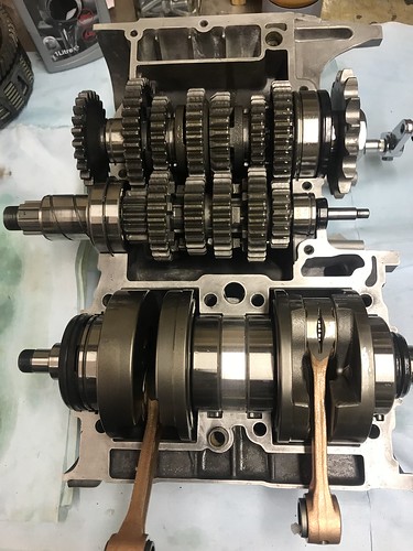 IMG_5584 IMG_5584 by Alan Kelly, on Flickr Next a test fit was carried out to check that after the top case was fitted all shafts and crank revolved OK, and that the gear selector system / gear clusters work OK with all the modified and replacement parts. And once I was happy with all I finally fitted the top case for good with sealant, so that the bottom end was now finally "buttoned up" 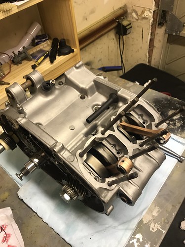 HMZO2906 HMZO2906 by Alan Kelly, on Flickr Last night progressed to assembling the primary drive, and have decided the fit a new Makita Clutch basket, dampers and springs (Kindly supplied by Norbo thanks mate) to replace the worn items. Also clutch is fitted with new plates (both the cork and steel plates as he original were just scrap!!) And lastly as the R/H case has been converted to a window type, I decided to replace the original tatty clutch spring bolts and spring washers with stainless items made at work. 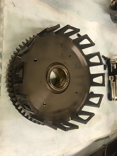 IMG_5562 IMG_5562 by Alan Kelly, on Flickr 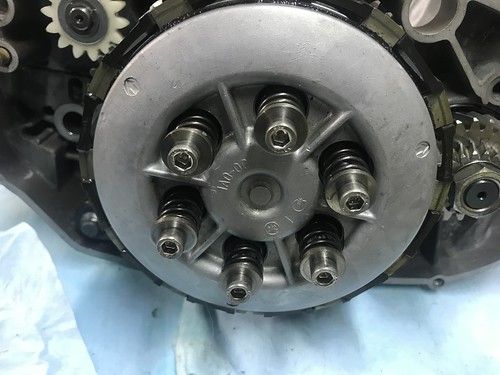 IMG_5626 IMG_5626 by Alan Kelly, on Flickr 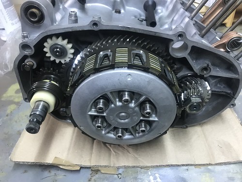 Also found during the original engine strip down / inspection that the kick starter idler was suffering from the normal wear of the bearing bush, that then causes it to wobble on the shaft, so again decided to turn up a new PB bush at work to replace the worn item and remove the "wobble" :-). 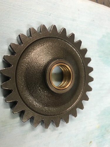 IMG_5599 IMG_5599 by Alan Kelly, on Flickr And with everything now fitted IMG_5628 by Alan Kelly, on Flickr Have for now temporarily fitted he outer case with the customary "window" which looks really cool :-) 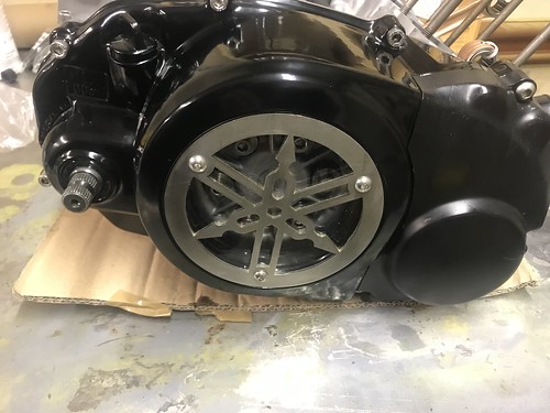 IMG_5634 IMG_5634 by Alan Kelly, on Flickr 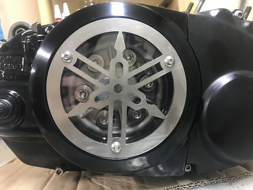 IMG_5632 IMG_5632 by Alan Kelly, on Flickr Next part of the build will be to work on the other side and replace the knackered stator with a rewound item. And then once this is back and fitted, will continue to build and assemble the top end once the barrels / cylinder head have been painted and "cooked" in the kitchen when the wife is out!! Think that's all for now. Catch up again soon. Best and kindest regards to all Al. |
|
|
|
Post by dusty350 on Nov 6, 2018 21:33:38 GMT 1
Looks great Al It's so worth changing any worn parts at this stage to save problems in the future, as you say. Costs more now, but less in the long run ! You are not far off now Dusty |
|
|
|
Post by alankelly on Nov 6, 2018 21:38:13 GMT 1
Hi Dusty
Yes the end is in sight!!
Keep up the good work yourself and and catch up soon.
Best wishes Al.
|
|
|
|
Post by alankelly on Nov 12, 2018 21:54:14 GMT 1
Hi all Looks like its RD barrels and head for tea tonight!!! 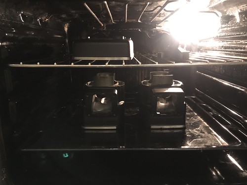 IMG_5667 IMG_5667 by Alan Kelly, on Flickr Catch up soon Al |
|
|
|
Post by bezzer on Nov 13, 2018 0:36:33 GMT 1
Hi all Looks like its RD barrels and head for tea tonight!!! IMG_5667 by Alan Kelly, on Flickr Catch up soon Al Three things spring to mind Al, you are either : 1. Single. 2. You have a Mrs but she is out. 3. You have a Mrs but she is on holiday. 🤣 I tried a similar thing years ago with Duckhams chainwax, but even with all the windows and doors open she still went apoplectic with rage when she returned from the weekly shop 😬 |
|
|
|
Post by 4l04ever on Nov 13, 2018 10:43:07 GMT 1
I baked my barrels and head in the oven too. Gas mark 5 for 20 mins, then leave in overnight to cool off. Did have to leave the window open though. :-)
|
|
|
|
Post by alankelly on Nov 13, 2018 13:40:30 GMT 1
Hi Bezzer
Sorry but none of the above
Just a very understandings wife and two boys who are seeing their dad having a mid life crisis😁😁
|
|
|
|
Post by alankelly on Nov 13, 2018 20:49:20 GMT 1
Hi all Just another update on the Yellow peril (It should be called a bottomless money pit!!!) Started to "dry assemble" the top end tonight after my cooking session last night!!! Engine is really starting to come together. And after looking on Norbo "toy store", heart ruled the head (and wallet) and decided to replace the original tatty Yam head bolts with something more pretty! (Thanks Norbo) 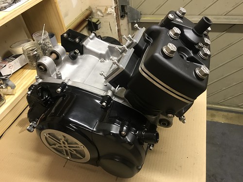 IMG_5686 IMG_5686 by Alan Kelly, on Flickr 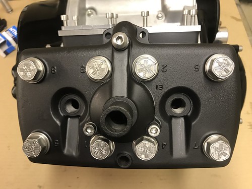 IMG_5683 IMG_5683 by Alan Kelly, on Flickr Also as I had a bit of spare time in the machine shop the last few days, and have decided to do as Dusty did in an earlier engine build. And I have now bored out my outer cover where the Gear selector shaft pokes out, and have fitted a nice needle bearing assembly to repair the worn hole, to again reduce any inbuilt binding of the shift system shaft. (And its a nice easy mod') 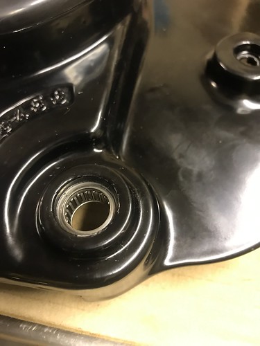 IMG_5681 IMG_5681 by Alan Kelly, on Flickr 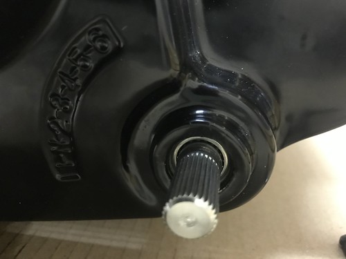 IMG_5682 IMG_5682 by Alan Kelly, on Flickr Plan now will be to turn up a couple of dust shields to keep the muck out, and this improvement will be complete :-) Also been looking on the forum and other places about the advantages or disadvantages of possibly adding reed spacers. And the general consensus seems that adding a 6mm spacer between the barrel and reed block helps out the bottom end for a bit of sacrifice of the top end as it increases the gas flow around the reeds themselves and the volume with the lower crankcases slightly. So found a bit of alloy plate looking for a home, and over a couple of lunchtimes have converted it to a couple of nice reed spacers :-). 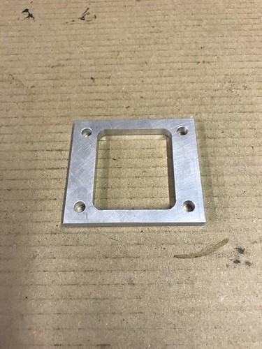 IMG_5676 IMG_5676 by Alan Kelly, on Flickr 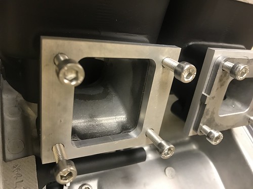 IMG_5678 IMG_5678 by Alan Kelly, on Flickr 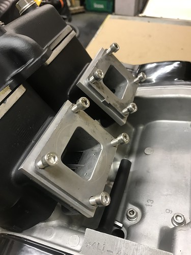 IMG_5684 IMG_5684 by Alan Kelly, on Flickr Next stage of the build is to next check piston ring gaps etc and finally build and "button up" the top end, and then make a leak down kit up at work and test. Fit the refurb oil pump where it arrives back from that master of oil pumps Arrow (Thank you arrow) And (told you it was a money pit) replace the cooked / knackered stator and other old ignition parts with a new new Power Dynamo system from Martin at M B designs. (Thank you Martin) Think that's all for now. Catch up again soon. Best wishes Al. |
|
|
|
Post by alankelly on Nov 22, 2018 21:46:27 GMT 1
Hi all Hope all is well Did a leak down test with my homemade test kit (Pictures to follow) and losing about 2 psi over the 5 min test time (Pressurized to 32MPa (5psi) on my digital gauge Found leak OK with the soapy water test, and its a very small leak on the intakes on the first gasket between the barrel and my reed spacers. 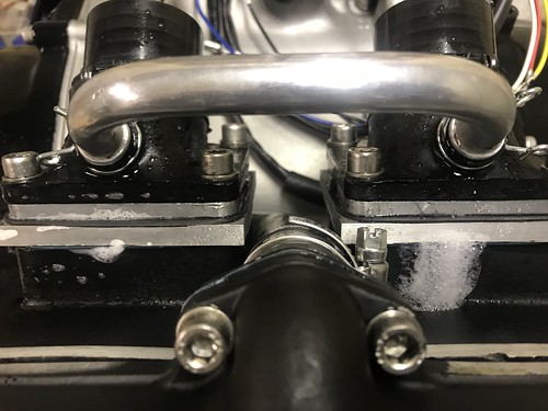 IMG_5749 IMG_5749 by Alan Kelly, on Flickr It looks like a fault with the gasket itself as the leak on both inlets and is in the same place. At it look like a very small leak thru the material itself as I used a smear of silicon on the intake gaskets on assembly to try and ensure a leak free test. Question I have is, can I just ditch the gaskets and just reassemble with with black RTV instant gasket as the crankcases are joined in the same way? Thought I would just ask the question. (As my old boss used to say, "better to ask a stupid question than fix a stupid mistake!" Many thanks in advance to all Best wishes Al. |
|
|
|
Post by dusty350 on Nov 23, 2018 8:17:56 GMT 1
Hi Al It's really coming on now mate I always use genuine Yamaha gaskets for the reed blocks, allied with clear silicone on both sides. It's amazing how many air leaks are found in this area, but better here than say a base gasket ! You could try just silicon, but I've never done it that way myself. Dusty |
|
|
|
Post by bazzer5115 on Nov 23, 2018 9:13:04 GMT 1
The problem with silicone is it gets affected by petrol & petrol vapour and over time can turn into a type of jelly,seen it many times.
I never use it on fuel systems,I always use yamabond on reed blocks as well as genuine gaskets.
Also I have found that it’s worth checking the bolts on the reed blocks occasionally as I found they tend to loosen over time as the rubber tends to compress. So even if it passes your leak down test at the time of rebuild,it may leak slightly from this area over time,pull in air and seize that cylinder,I know this because it happened to me!!
|
|
|
|
Post by bazzer5115 on Nov 23, 2018 9:55:49 GMT 1
The problem with silicone is it gets affected by petrol & petrol vapour and over time can turn into a type of jelly,seen it many times.
I never use it on fuel systems,I always use yamabond on reed blocks as well as genuine gaskets.
Also I have found that it’s worth checking the bolts on the reed blocks occasionally as I found they tend to loosen over time as the rubber tends to compress. So even if it passes your leak down test at the time of rebuild,it may leak slightly from this area over time,pull in air and seize that cylinder,I know this because it happened to me!!
|
|
|
|
Post by alankelly on Nov 23, 2018 9:58:03 GMT 1
Hi all
Thanks for the advice
Been thinking 😁
Looking at the inlet barrel casting the tiop and bottom lands are a bit small to get a good seal with just the 4 m6 screw so I will look at the reed spacer design I made and see if I can machine an o ring groove either side and use an o ring to create the seal and get rid of the paper gaskets
It’s what was on my old hiinda as they sealed the inlet rubber to the head using as standard o ring seal
As normal space is tight on the spacer but should be easy to experiment with my home made spacers 👍👍
Will post the mod if it works out ok
Best wishes Al
|
|
|
|
Post by Tobyjugs on Nov 23, 2018 10:08:51 GMT 1
Good idea. There is not much room for the O-ring.
Square flanges with a bolt in each corner can deform when overtightened. The corners can bend in leaving less pressure in the middle leading to leaks.
|
|
|
|
Post by alankelly on Nov 23, 2018 10:17:40 GMT 1
Ps
Think I will also swap out the 4 bolts for studs and nuts like the exhaust as studs produce better clamping plus saves possible strippig out of the already worn 40 year old threads in the barrels sometime in the future👍
Best wishes Al
|
|
|
|
Post by Tobyjugs on Nov 23, 2018 10:24:55 GMT 1
I think studs will make maintenance more difficult.
|
|
|
|
Post by alankelly on Nov 23, 2018 10:40:04 GMT 1
Hi Tobyjugs
Not sure if studs will hamper things as you still need to pull the reed block back a good distance to clear the reeds from the barrel but will certainly look at this too so thanks for the tip👍
Looks like it’s going to again be a busy time next week in the evenings again but love to make things better than original and will (if the o ring seal is possible both make maintenance easier and remove the need to also use a smear of sealant to get a good seal with the standard gasket arrangement
Best wishes Al
|
|
|
|
Post by alankelly on Nov 25, 2018 23:12:45 GMT 1
Hi all. Need some help / advice please. Been leak down testing my rebuild this weekend, and could only achieve the following result. Pressure to 5PSI After 2 min pressure dropped to 4 PSI After 5 mins pressure drops to 3 PSI and then continue to very slowly degrade Looked everywhere on the outside with the soapy water trick but no bubbles, so suspected leak is either crankcase spit line or a crank seal issue. As I thought the above and as I have decided to replace the pattern crank seals with genuine Yamaha ones, I have now stripped the engine back down (which to be honest is not such a bad job being a 2 stroke.) And as I suspected either a crankcase seal leak or a crank seal leak, I have had a close inspection, and I think the source of my leak is some "wear" grooves on the seal surface of the primary gear (Where the original seal was locating) that may be causing the seal not to seat correctly on the surface so creating a very small leak. 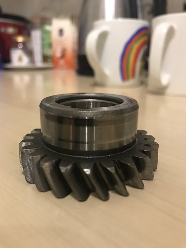 IMG_5772 IMG_5772 by Alan Kelly, on Flickr So my question is please, can I polish this surface by spinning in the lathe to "smooth" out the grooves? So that the seal surface is more even without any defined "ridges" that could prevent the seal lip from sealing correctly as I suspect that pronounced seal wear groove edges may be in contact with the seal lip causing it not to seal around the gear diameter correctly. Not looking to create a perfectly cylindrical surface again but just "smooth" out seal area to produce a better / flatter seal running diameter for the seal lip to seal on. Any advice always welcome. Best wishes Al. |
|


