|
|
Post by jon on Mar 24, 2016 10:06:23 GMT 1
Mark, out of interest how close to the bearing journal are you going to be able to weld?
There seems a lot of meat/metal on the full case where the stator sat that would get in the way of welding close up to the journal. Will you remove more prior to weld?
Jon
|
|
|
|
Post by yamark on Mar 24, 2016 18:26:43 GMT 1
Mark, out of interest how close to the bearing journal are you going to be able to weld? There seems a lot of meat/metal on the full case where the stator sat that would get in the way of welding close up to the journal. Will you remove more prior to weld? Jon Great question Jon. The welds get quite close with the exception of the rear and underside (where the vertical webs get in the way). If you can imagine, there will be another section of crankcase welded behind the left cylinder. This is for the outrigger gearbox bearing and also acts as the point at which the left engine cover is mounted to. So that section is almost welded twice.
The underside is near impossible to access, so its welded as best as it can be. Some of the webs are then machined back and a support plate is bolted in place bridging the join for added strength. The plate goes over the lower crankcase studs and is held by the underside nuts when the engine is assembled.
The last option is to v out and weld internally where the left lab seal sits, but as the cases need to be apart, the danger will be distorted crankcases.
Hope that all makes sense, but all will be revealed soon
Regards Mark 
|
|
|
|
Post by jon on Mar 24, 2016 21:16:28 GMT 1
Mark, I am an engineer by 'trade', and a self taught welder.
Unless you weld as far as you can get to the 3rd journal, there will be voids that will get full of fuel. This may effect the third cylinder.
Jon
|
|
|
|
Post by yamark on Mar 25, 2016 13:54:37 GMT 1
Mark, I am an engineer by 'trade', and a self taught welder. Unless you weld as far as you can get to the 3rd journal, there will be voids that will get full of fuel. This may effect the third cylinder. Jon Jon, sorry I misunderstood your question. I answered in respect of the strength of the crankcases, not the sealing of them.
The vertical join of the cases, is midway on the left hand labyrinth seal (the crank will have 2 lab seals, 6 main bearings). So all the primary chambers are sealed.
Hope that explains it.
Mark
|
|
|
|
Post by jon on Mar 25, 2016 14:02:12 GMT 1
Mark, that makes more sense now you've explained.
Jon
|
|
|
|
Post by KevtheRev on Mar 26, 2016 0:20:29 GMT 1
What way will the crank pins be spaced man ? I mean how many degrees apart ?
|
|
|
|
Post by yamark on Mar 26, 2016 18:42:49 GMT 1
What way will the crank pins be spaced man ? I mean how many degrees apart ? Kev, 120 degrees mate, should run pretty smooth |
|
|
|
Post by dusty350 on Mar 26, 2016 18:54:28 GMT 1
Suspense is building....  Dusty  |
|
|
|
Post by KevtheRev on Mar 26, 2016 19:24:57 GMT 1
What way will the crank pins be spaced man ? I mean how many degrees apart ? Kev, 120 degrees mate, should run pretty smooth Ah , just wondered . I never had any engineering training . And when I got my first few bikes never really had any tools either . Generally I used a Vise-Grips and a rock for routine maintenance . Thankfully I've learned a bit since those early days . Keep up the good work , cant wait to hear how she goes for you . Oh , and how will you organize the ignition ?? |
|
|
|
Post by yamark on Mar 26, 2016 19:44:28 GMT 1
Thanks Kev, I hope you didn't squash your fingers when using the rock .
The ignition is tricky, but the plan is to use three trigger coils (generator area), and three secondary coils under the tank. To explain it would bore the tits off you, so I won't,
Cheers Mark |
|
|
|
Post by jon on Mar 26, 2016 20:44:31 GMT 1
Interesting yamark about your plan for the triggers.
I know what you mean about the smooth running of a triple. I have a V6 golf, which being a four stroke is effectively the same timing between firing. My colleague at work also has a speed triple, which is very smooth.
My first guess around this problem would have been to machine off the Hall effect triggers of an LC flywheel, and let in 3 at 120 degrees apart. You could even adjust the pickup to further away if they were taller.
Jon
|
|
|
|
Post by yamark on Mar 27, 2016 8:33:44 GMT 1
Really like your thinking Jon. I toyed with 3 magnets relocated in the flywheel, which would work. But I was worried about the charge coils (high and low speed) having 2/3rds of the time to charge the capacitor. So I thought I'd have a weaker spark. What do you think?
Mark |
|
|
|
Post by jon on Mar 27, 2016 8:53:32 GMT 1
Mark, I'm not too sure to be honest.
Either way you are going to have a lot of head scratching.
At least being an LC you will not have to worry about the tacho electrics.
Jon
|
|
|
|
Post by Tobyjugs on Mar 27, 2016 9:19:45 GMT 1
Thanks Kev, I hope you didn't squash your fingers when using the rock .
The ignition is tricky, but the plan is to use three trigger coils (generator area), and three secondary coils under the tank. To explain it would bore the tits off you, so I won't,
Cheers Mark You could bore the tits off me as i find it interesting. Couldn,t you use some kind of programable ignition, on the ignitech i had to ground the ignition coils, and the cdi is replaced by the ignition unit? I would just like to say all things electrical are a little bit like black magic in my eyes  |
|
|
|
Post by yamark on Mar 27, 2016 9:26:47 GMT 1
Mark, I'm not too sure to be honest. Either way you are going to have a lot of head scratching. At least being an LC you will not have to worry about the tacho electrics. Jon Jon, You are so right about the tacho electrics.
I used to diagnose electronic ignition faults when I worked for Honda GB back in the day. So I remember how most of them work from the late 70's and early 80's, but like everything the memory is failing as the years pass.
|
|
|
|
Post by yamark on Mar 27, 2016 10:11:05 GMT 1
Thanks Kev, I hope you didn't squash your fingers when using the rock .
The ignition is tricky, but the plan is to use three trigger coils (generator area), and three secondary coils under the tank. To explain it would bore the tits off you, so I won't,
Cheers Mark You could bore the tits off me as i find it interesting. Couldn,t you use some kind of programable ignition, on the ignitech i had to ground the ignition coils, and the cdi is replaced by the ignition unit? I would just like to say all things electrical are a little bit like black magic in my eyes Hi Tobyjugs, at the risk of boring everyone. The LC works by charging a capacitor in the cdi box. Half a rotation of the flywheel is needed for the 2 coils to charge the capacitor(these are the high/low speed windings, their outputs are combined to give a constant output across the rev range). With the capacitor charged the magnet on the outside of the flywheel passes under the pickup coil and signals the capacitor to discharge in the cdi box. This charge(like a pulse of electricity) goes to the secondary coils under the tank. On the LC the coil has 2 output leads which means both spark plugs fire. One piston is at BDC so this spark is wasted, the other piston at TDC makes the bang we all like. A second magnet 180 on the flywheel makes both plugs flash together 1/2 a rev later. So the limiting factor on the LC is the generator source coils(high/low coils), they need 180 degrees to create energy, I need 120 degrees.
Both of Harry's triples use the Dyna S system, so he has solved the problem. I understand Cinder is going over to the same system for his 700cc LC four as the LC's capacitor struggles to fire 4 plugs. Harry uses a cbr600 generator and flywheel, then 3 Dyna S coils with 3/ 3ohm secondary coils. This gives 35,000 v at the plugs and is the system I'll probably adopt. Everybody still awake Cheers Mark
|
|
|
|
Post by jon on Mar 27, 2016 10:32:03 GMT 1
Mark, surely whatever system you replace the original CDI with, you will need 3 triggers per revolution?
Jon
|
|
|
|
Post by KevtheRev on Mar 27, 2016 10:51:52 GMT 1
You wont bore me man , I'm very interested . Hope she runs sweet as a sweet thing for you .
|
|
|
|
Post by dusty350 on Mar 27, 2016 11:30:34 GMT 1
Hi Mark It's all dutch to me, but I know you know what you are doing, and I know it will work when it's all fitted. This is the thing with specials - so much work is done beneath the skin that often never gets seen or thought about, all the more with your unique build. It's gonna be an awesome bike for sure Dusty |
|
|
|
Post by cb250g5 on Mar 27, 2016 11:44:28 GMT 1
How high are you thinking of revving this beasty?
The stock genny can charge the CDI sufficiently at up to 12,000 rpm. So if you want 50 % more sparks, I'd suggest it would be OK up to at least 8,000 rpm, enough to get you going anyway.
|
|
|
|
Post by jon on Mar 27, 2016 12:08:52 GMT 1
cb250g5, while your maths seem logical, im not sure it works like that.
You see it's more about trying to get enough charge from 1 revolution of the crank rather than 2. This is irrespective of RPM.
I would have also thought the limitation is with the original system. I'm not an expert on the latest ignitions, but thought they got power from a battery to exite the secondary coils once a trigger is given.
Jon
|
|
|
|
Post by yamark on Mar 27, 2016 12:36:02 GMT 1
Mark, surely whatever system you replace the original CDI with, you will need 3 triggers per revolution? Jon You are spot on Jon. The Dyna system needs 12v to the source coils. I need 3 of these coils. They are triggered by a magnet on a small spinning rotor mounted on the crank. So I will have 2 halves to the system. Where the original flywheel sits will be a CBR600 flywheel, but with the open end outward. A plate covers this and has the alternator windings on the back of this new "stator plate". The plate mounts to the genny cover as the genny cover will be machined down. So that sorts the charging. The plate (about 8mm thick) then acts as a mount for the 3 Dyna coils to be mounted outboard the plate.(a bit like a RD400c or d). The trigger rotor passes through a central hole in the plate and the ignition wires also pass through the plate to the secondary coils.
So 1 trigger magnet, 3 powered source coils, 3 secondary coils, CBR600 3 phase alternator - easy
|
|
|
|
Post by cb250g5 on Mar 27, 2016 13:28:57 GMT 1
I've no doubt that a modern battery powered ignition would be the best, if not cheapest way to go.
However alternators, and this is a simple single phase alternator, all be it with a slow speed & high speed winding, don't produce more power just because they spin faster, the frequency of the AC waveform just increases.
Take a google for "alternator power vs rpm" & you'll see plenty of graphs of the rectified DC voltage quickly reaching about 90% of max & then not really gaining much more for revving higher. One reason alternators have replaced dynamos. So you will have enough power at lower revs to handle the number of sparks that is needed at higher revs, in my humble opinion, based only on theory, not having seen the circuit diagram of the yam CDI.
I bet the cap is just charged from a half wave rectified version of the AC coming in. 1970's electrics.
|
|
|
|
Post by yamark on Mar 27, 2016 13:37:06 GMT 1
I found this image of Harry's LC triple. If you look closely, you can see the added plate that the generator and ignition are attached to. Much easier to see than for me to describe.
Oh and thanks, Jon, Kev, Dusty, cb250g5 for the encouragement and interest.
I hope to post the images of the centre cylinder alterations tomorrow
Frankenstein LC is slowly getting there! |
|
|
|
Post by yamark on Mar 28, 2016 18:23:54 GMT 1
The 2nd stage now the crankcases are the correct width, is to modify the centre cylinder. Because of the curve on the outside, the centre has to be machined flat. The outer cylinder's are placed on first
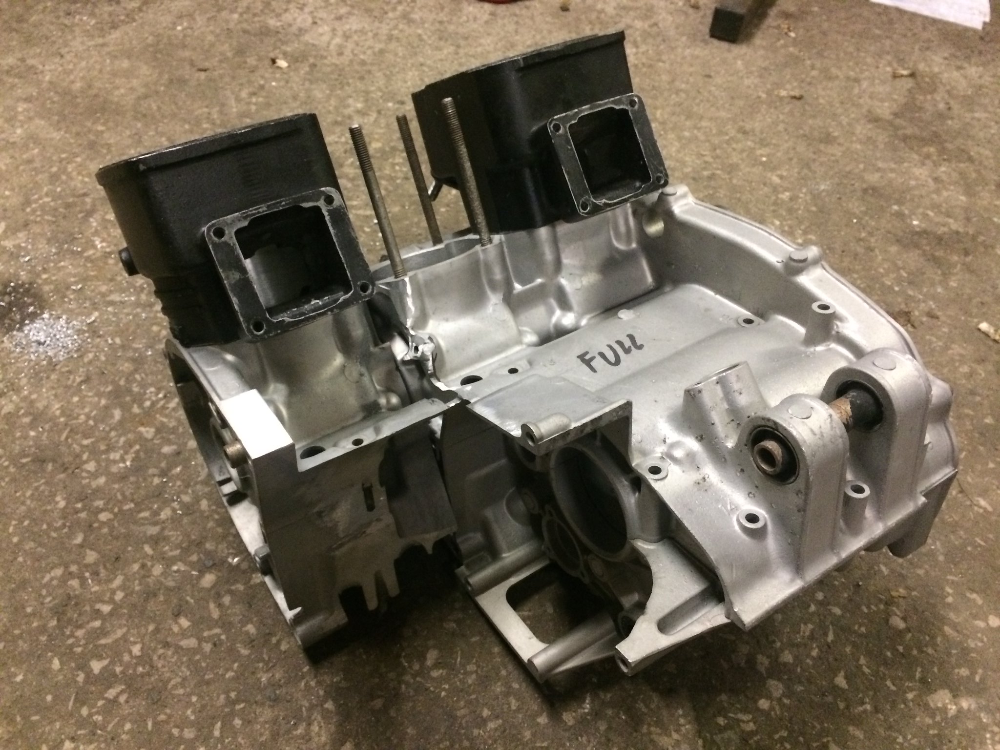 IMG_1474 IMG_1474
 IMG_1475 IMG_1475
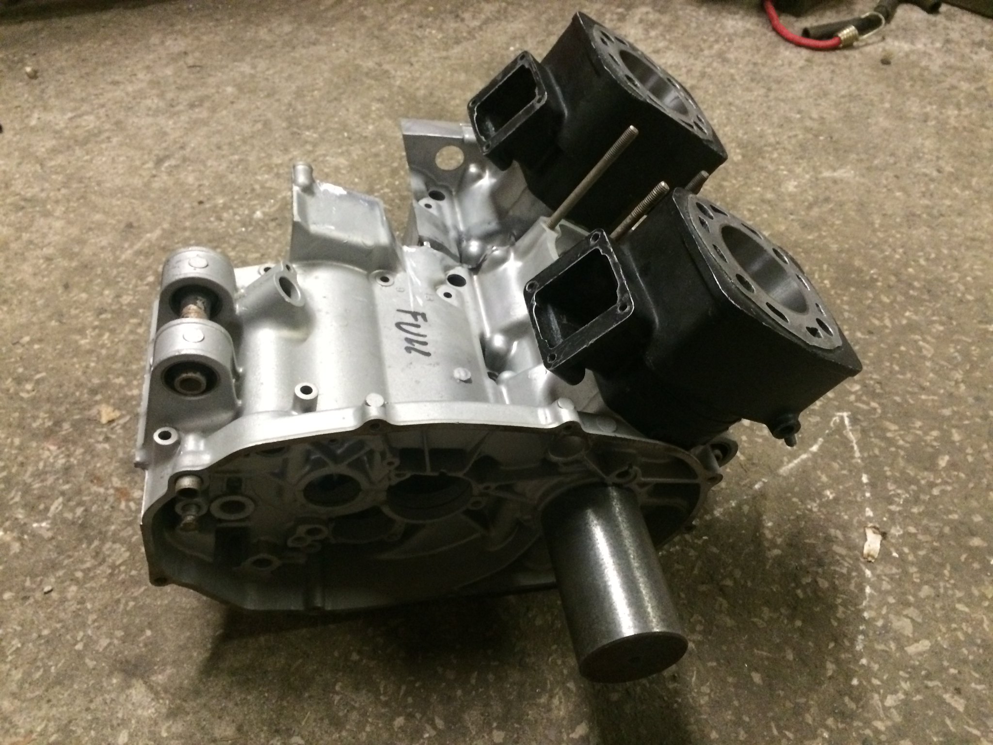
Next the centre is machined to keep an even spacing. You obviously loose the coolant drain.
 IMG_1479 IMG_1479
Some material then has to be removed to restore the internal water passageway.
 IMG_1480 IMG_1480
A plate is then welded to seal the water jacket back up, and the cylinder slots in between the 2
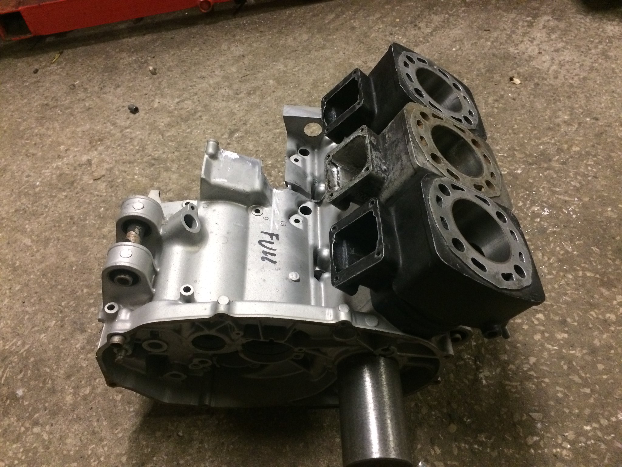 IMG_1481 IMG_1481
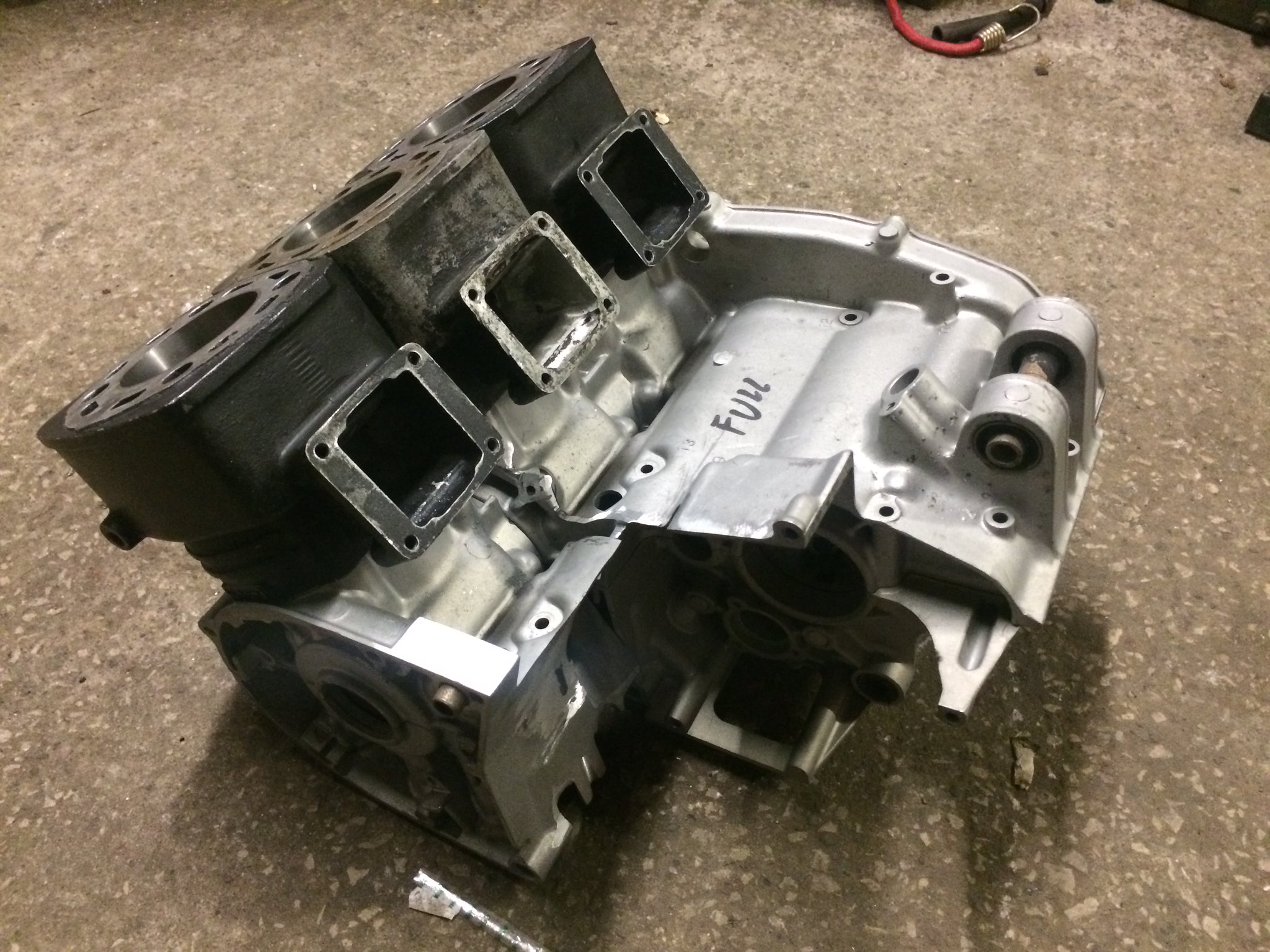 IMG_1482 IMG_1482
|
|
|
|
Post by iwantalc on Mar 28, 2016 18:52:29 GMT 1
cant you use the ignition system off a 3 cylinder 2 stroke like a Suzuki gt or Kawasaki kh ..just a thought
|
|
|
|
Post by yamark on Mar 28, 2016 20:00:56 GMT 1
cant you use the ignition system off a 3 cylinder 2 stroke like a Suzuki gt or Kawasaki kh ..just a thought Cheers for the idea iwantalc, this is why I love this forum - fellow 2 stroke nuts putting their ideas forward to solve problems. It also helps me confirm my thoughts or a new idea is suggested.
I looked into Newtronic and Boyer, for the kh 250 or 400. After some research the secondary coils can overheat (heard this a few times).
The Dynatek system is used by drag bike racers in the states, and seems to be the most reliable. It's also a known quantity. The Dynatek is a bit dearer and I'll have to fabricate 3 coils onto the stator, but shouldn't be too difficult.
Harry had a Boyer system on his triple and it coughed and spluttered when hot, which convinced me to replicate his setup.
Mark
|
|
|
|
Post by Tobyjugs on Mar 28, 2016 21:30:41 GMT 1
Can't wait to se the cylinder head. It still seems a bit old school with all the coils
|
|
|
|
Post by Slabsideian on Mar 28, 2016 21:51:44 GMT 1
Some very clever sh*t going on ere!! Watching with great interest.
Keep it going and all the best
|
|
|
|
Post by yamark on Mar 28, 2016 22:58:33 GMT 1
Can't wait to se the cylinder head. It still seems a bit old school with all the coils The cylinder head is a bit bizarre. You'll have to wait and see.
But stage 3 is the gearbox outrigger bearing section, and moving the rear engine mounts!
|
|


